Service Manuals, User Guides, Schematic Diagrams or docs for : . Car Manuals Subaru Impreza 2001-2002.2004-2007 Approved Subaru Impreza 2004 WRX STi 08. MECHANISM AND FUNCTION 35. MANUAL TRANSMISSION AND DIFFERENTIAL (6MT) 07. Driver-controllable Center Differential System
<< Back | HomeMost service manuals and schematics are PDF files, so You will need Adobre Acrobat Reader to view : Acrobat Download Some of the files are DjVu format. Readers and resources available here : DjVu Resources
For the compressed files, most common are zip and rar. Please, extract files with Your favorite compression software ( WinZip, WinRAR ... ) before viewing. If a document has multiple parts, You should download all, before extracting.
Good luck. Repair on Your own risk. Make sure You know what You are doing.
Image preview - the first page of the document
>> Download 07. Driver-controllable Center Differential System documenatation <<
Text preview - extract from the document
DRIVER-CONTROLLABLE CENTER DIFFERENTIAL SYSTEM
MANUAL TRANSMISSION AND DIFFERENTIAL
7. Driver-controllable Center Differential System
A: FEATURES
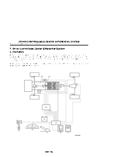
! The driver-controllable center differential system consists of a planetary gear set and electro-
magnetically engaged variably controlled multi plate clutches, distributing the drive torque to the
front and rear wheels at a ratio of 35 : 65. The driver can optionally change the locking rate of the
center differential.
! The system optimally controls the restricting action of the center differential using a computer and
works together with the ABS control.
(20) (21)
(15) (1)
(16)
(2)
(17) (19)
(18)
(12)
(11) (3)
(10)
(22)
(9)
(13)
(6)
DCCD
MANU
(8)
(14)
(7) (5) (4)
MT-00982
6MT-18
DRIVER-CONTROLLABLE CENTER DIFFERENTIAL SYSTEM
MANUAL TRANSMISSION AND DIFFERENTIAL
(1) Wheel speed sensor (RR) (12) Brake light switch
(2) Rear differential oil temperature switch (13) Throttle position sensor
(3) Wheel speed sensor (RL) (14) Accelerator pedal
(4) Manual mode switch (15) Wheel speed sensor (FR)
(5) Control dial (16) Lateral G sensor
(6) Driver-controllable center differential unit (17) Input from main reduction gear
(7) Parking brake switch (18) Front output
(8) Driver-controllable center differential indicator light (19) Rear output
(9) Battery (20) Transmission assembly
(10) ABSCU & H/U (21) Center differential
(11) Wheel speed sensor (FL) (22) ABS monitor signal
Control Auto mode Manual mode
Hand brake control yes yes
Brake control yes yes
Center differential control yes yes
Fail-safe control yes yes
ABS control yes yes
Throttle respondent torque control yes yes
Slip control yes no
Tight cornering control yes yes
Volume control no yes
Cornering control yes no
Rear differential oil control yes yes
! Hand brake control
When the hand brake is operated, the current to the coil is lowered to forcibly free the center differ-
ential.
! Brake control
Controls the center differential restriction torque toward the free state in response to brake switch
input.
! Center differential control
Based on throttle respondent torque control and slip control as basic controls, the differential restric-
tion torque of the center differential is controlled between the free state and locked state through
PWM control. Also, information received from other various switches and sensors are used in cor-
recting the instruction torque for center differential control.
! Fail-safe control
If a failure such as breakage of the coil drive element is detected, the coil driving power is turned off
and warning indication is given on the meter cluster at a 1 Hz cycle to call attention of the driver. If
a failure occurs in any of the sensors, a fixed value is substituted for the value from the failed sensor
to maintain control as usual, while activating a warning indication on the meter at a 1 Hz cycle to
call attention of the driver.
! ABS control
When the ABS operates, the ABSCU & H/U outputs an activating signal to the center differential
control unit to decrease the differential restriction torque of the driver-controllable center differential.
6MT-19
DRIVER-CONTROLLABLE CENTER DIFFERENTIAL SYSTEM
MANUAL TRANSMISSION AND DIFFERENTIAL
! Throttle respondent torque control
Controls the restriction torque of the center differential in response to the throttle opening. The re-
striction torque of the center differential calculated for each mode is corrected using particular val-
ues, however, basically toward the locked state when the throttle is wide open or toward the free
state when the throttle is fully closed.
! Slip control
Controls the restriction torque of the center differential based on the amount of slip derived from the
speed of four wheels.
! Tight cornering control
A correction value is calculated from the left and right wheel speed ratio and applied to the restric-
tion torque of center differential, which is derived from the throttle respondent, slip control, etc.
! Volume control
By operating the control dial, the driver can optionally control the restriction torque of the center dif-
ferential.
! Cornering control
The restriction torque of center differential is controlled based on a value derived from the throttle
opening, lateral G sensor, four wheel speeds, etc.
! Rear differential oil control
When the rear differential oil temperature rises and the oil temperature switch activates, the center
differential restriction torque is controlled toward the free state.
6MT-20
DRIVER-CONTROLLABLE CENTER DIFFERENTIAL SYSTEM
MANUAL TRANSMISSION AND DIFFERENTIAL
B: INPUT AND OUTPUT SIGNALS
Name Function
Driver-controllable center differential In response to the signal from the driver-controllable center differential control unit, the cur-
rent is varied to change the transmitting torque of the multi-plate clutch and control the dif-
ferential torque.
Driver-controllable center differential Processes the signals from various sensors and switches and controls the current to the
control unit driver-controllable center differential.
Lateral G sensor Sends information on acceleration of the vehicle in lateral directions to the driver-controlla-
ble center differential control unit.
Driver-controllable center differential Indicates the locking rate of the center differential in a range from 0% to 100%.
indicator light
Manual mode switch Switches the driver-controllable center differential control mode between auto and manual.
Control dial Enables to manually select the locking rate of the center differential in a range from 0% to
100%.
Rear differential oil temperature Sends a signal to the driver-controllable center differential control unit if the rear differential
switch oil temperature rises abnormally.
Parking brake switch Sends information on the parking brake operational status to the driver-controllable center
differential control unit.
Stop light switch Sends information on the brakes' operational status to the driver-controllable center differ-
ential control unit.
Throttle position sensor Sends information on the throttle valve opening to the driver-controllable center differential
control unit.
ABSCU & H/U Sends ABS monitor signals to the driver-controllable center differential control unit.
6MT-21
DRIVER-CONTROLLABLE CENTER DIFFERENTIAL SYSTEM
MANUAL TRANSMISSION AND DIFFERENTIAL
(1)
(2)
(3)
(4)
(14)
(15)
(5)
(6)
(7)
(16)
(8)
(9) (22)
(10) (17)
(11) (18)
(12) (19)
(20)
(21)
(13)
MT-00983
6MT-22
DRIVER-CONTROLLABLE CENTER DIFFERENTIAL SYSTEM
MANUAL TRANSMISSION AND DIFFERENTIAL
(1) Battery (12) Indicator light
(2) Ignition relay (13) ABSCU & HU
(3) Stop light switch (14) Throttle position sensor
(4) Driver-controllable center differential relay (15) Engine control unit
(5) Combination meter (16) Driver-controllable center differential
(6) Driver-controllable center differential indicator light (17) Parking brake switch
(0% locked)
(7) Driver-controllable center differential indicator light (18) Manual mode switch
(15% locked)
(8) Driver-controllable center differential indicator light (19) Rear differential oil temperature switch
(35% locked)
(9) Driver-controllable center differential indicator light (20) Control dial
(65% locked)
(10) Driver-controllable center differential indicator light (21) Lateral G sensor
(85% locked)
(11) Driver-controllable center differential indicator light (22) Driver-controllable center differential control unit
(100% locked)
6MT-23
DRIVER-CONTROLLABLE CENTER DIFFERENTIAL SYSTEM
MANUAL TRANSMISSION AND DIFFERENTIAL
C: DRIVER-CONTROLLABLE CENTER DIFFERENTIAL
! The driver-controllable center differential consists of a differential case, planetary carrier, plane-
tary gears, electro-magnetic coils, armature, main clutch (multi-plate clutch), pilot clutch, and ball
bearings.
! The engine torque enters the differential case from the transmission's driven shaft. The torque
from the differential case is divided into front and rear directions at the planetary carrier; the torque
to the front is transferred from the planetary carrier through the planetary gears to the sun gear,
while the torque to the rear is transferred from the transfer drive gear (integrated with the planetary
carrier) through the driven gear to the propeller shaft.
! If either of the front or rear wheels spins, the driver-controllable center differential controls the dif-
ferential action between the front and rear wheels.
(7) (8)
(9)
(1)
(2)
(3)
(6) (5) (4)
MT-00908
(1) Pilot clutch (6) Differential case
(2) Planetary carrier (7) Main clutch
(3) Electro-magnetic coil (8) Planetary gear
(4) Electro-magnet (9) Ball bearing
(5) Armature
6MT-24
DRIVER-CONTROLLABLE CENTER DIFFERENTIAL SYSTEM
MANUAL TRANSMISSION AND DIFFERENTIAL
! When current flows through the electromagnetic coils, magnetism is generated at components in
the following sequence: electromagnet, differential case, armature (A). The armature is moved to
the right (B) by this magnetism causing the pilot clutch to engage, and a magnetic field is formed in
the area from the electromagnet, differential case, armature, and to the pilot clutch.
The pilot clutch locks the differential case side and cam 1 side together, thus the rotational speed
of the cam 1 and differential case are synchronized. The engagement of the pilot clutch is controlled
by adjusting the current flowing through the electromagnetic coils.
(1) (4)
(2)
(A)
(5) (B)
(3)
MT-00910
(1) Differential case (4) Pilot clutch
(2) Armature (5) Steel ball
(3) Cam 1
6MT-25
DRIVER-CONTROLLABLE CENTER DIFFERENTIAL SYSTEM
MANUAL TRANSMISSION AND DIFFERENTIAL
! When a speed difference occurs, a force (B) pushing the cam 2 to the left is generated at the steel
balls sandwiched between cam 1 and cam 2, pushing the planetary carrier to the left.
(3) (4)
(1)
(B)
(2)
MT-00934
(1) Steel ball
(2) Cam 1
(3) Planetary carrier
(4) Cam 2
6MT-26
DRIVER-CONTROLLABLE CENTER DIFFERENTIAL SYSTEM
MANUAL TRANSMISSION AND DIFFERENTIAL
! When the planetary carrier moves to the left (A) , the main clutch is engaged. The main gear locks
the planetary gears and the sun gear together to generate a differential action restriction torque.
(1) (2)
(3)
(A)
(4)
MT-00935
(1) Differential case
(2) Planetary carrier
(3) Main clutch
(4) Sun gear
6MT-27
DRIVER-CONTROLLABLE CENTER DIFFERENTIAL SYSTEM
MANUAL TRANSMISSION AND DIFFERENTIAL
D: LATERAL G SENSOR
A lateral G sensor is installed to the body at inside the console. The lateral G sensor detects the
acceleration of the vehicle in the lateral direction and controls the differential action restriction
torque.
(1)
MT-00912
(1) Lateral G sensor
6MT-28
DRIVER-CONTROLLABLE CENTER DIFFERENTIAL SYSTEM
MANUAL TRANSMISSION AND DIFFERENTIAL
E: MANUAL MODE SWITCH
The manual mode switch enables the driver to select the mode (auto mode or manual mode) by
pressing the switch each time.
MUNE
MT-00914
F: CONTROL DIAL
A rotary type switch is provided on the center console enabling the driver to optionally set the front-
rear differential action restricting torque in the range between locking rate 0% (free) to 100%
(locked). Also, detents are provided between free and locked positions.
L
CDIFF
MT-00915
6MT-29
DRIVER-CONTROLLABLE CENTER DIFFERENTIAL SYSTEM
MANUAL TRANSMISSION AND DIFFERENTIAL
G: DRIVER-CONTROLLABLE CENTER DIFFERENTIAL INDICATOR LIGHT
Driver-controllable indicator lights which indicate the locking rate of the center differential are pro-
vided in the meter cluster.
When the driver-controllable center differential is in the auto mode the "AUTO" at the upper part of
the meter cluster illuminates, and when in manual mode and the differential restriction torque is var-
ied manually the driver-controllable center differential indicator lights illuminate.
If the control unit detects a fault in a component or unit during self diagnosis, the driver-controllable
center differential indicator lights flash until the ignition switch is turned OFF.
Faulty components or units can be identified by reading diagnostic trouble codes (DTC), and faults
which occurred in the past can be retrieved from the memory.
(3)
(2) (1)
MT-00977
(1) Rear differential oil temperature warning light
(2) Driver-controllable center differential indicator light
(3) Driver-controllable differential auto mode indicator light
6MT-30
DRIVER-CONTROLLABLE CENTER DIFFERENTIAL SYSTEM
MANUAL TRANSMISSION AND DIFFERENTIAL
H: DRIVER-CONTROLLABLE CENTER DIFFERENTIAL CONTROL UNIT
The control unit is located behind the glove box at the front passenger's side.
If the control unit detects a fault in a component or unit during self diagnosis, the driver-controllable
center differential indicator light (FREE light at the bottom) flashes until the ignition switch is turned
OFF.
Faulty components or units can be identified by reading diagnostic trouble codes (DTC), and faults
which occurred in the past can be retrieved from the memory. The differential restriction torque of
the driver-controllable center differential is controlled based on signals from various sensors and
switches, ABS monitor signals and ABS wheel speed signals (from four wheels) from the ABSCU
& H/U, and by taking into account the conditions of the road surface and the vehicle.
A
(1) (2)
(2)
A◦ Jabse Service Manual Search 2026 ◦ Jabse Pravopis ◦ onTap.bg ◦ Other service manual resources online : Fixya ◦ eServiceinfo