Service Manuals, User Guides, Schematic Diagrams or docs for : . Car Manuals Subaru Impreza 2001-2002.2004-2007 Approved Subaru Impreza 2004 WRX STi 08. MECHANISM AND FUNCTION 47. HVAC SYSTEM (HEATER, VENTILATOR AND AC) 02. Cooling System
<< Back | HomeMost service manuals and schematics are PDF files, so You will need Adobre Acrobat Reader to view : Acrobat Download Some of the files are DjVu format. Readers and resources available here : DjVu Resources
For the compressed files, most common are zip and rar. Please, extract files with Your favorite compression software ( WinZip, WinRAR ... ) before viewing. If a document has multiple parts, You should download all, before extracting.
Good luck. Repair on Your own risk. Make sure You know what You are doing.
Image preview - the first page of the document
>> Download 02. Cooling System documenatation <<
Text preview - extract from the document
W1860BE.book Page 12 Tuesday, January 28, 2003 11:01 PM
COOLING SYSTEM
HVAC SYSTEM (HEATER, VENTILATOR AND A/C)
2. Cooling System
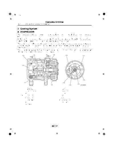
A: COMPRESSOR
The rotary type compressor consists of an integrally formed rotor and shaft, five vanes, and a cyl-
inder.
As the rotor turns, the vanes that are movably fitted in the rotor slide over the wall of the oval-shaped
cylinder while drawing, compressing, and discharging refrigerant gas.
The compressor shell has an oil separator at its rear end . High-pressure refrigerant gas having en-
tered this chamber is separated from the oil it contains before flowing out through the compressors
delivery port.
There is a check valve in the front housing to avoid reverse rotation of the compressor which would
otherwise occur when the compressor is stopped.
(5) (6) (8)
(3) (10) (11)
(4) (7)
(2)
(12)
(1) (15)
(13)
(9) (14) AC-00480
(1) Oil cut-off valve (9) Shaft
(2) Oil separator chamber (10) Suction port
(3) Shell (11) Cylinder
(4) Discharge port (12) Rotor
(5) Rear side plate (13) Vane
(6) Front side plate (14) Discharge valve
(7) Suction port (15) Discharge port
(8) Check valve
AC-12
W1860BE.book Page 13 Tuesday, January 28, 2003 11:01 PM
COOLING SYSTEM
HVAC SYSTEM (HEATER, VENTILATOR AND A/C)
1. PRESSURE RELIEF VALVE
This valve opens if the pressure of the high-pressure refrigerant gas rises to a dangerously high
level to release part of refrigerant into the atmosphere, thus protecting the compressor. The valve
is designed to limit the amount of released gas to the necessary minimum.
Valve opening pressure: 3.72 MPa (38 kgf/cm2)
Valve closing pressure: 1.8 MPa (17.5 kgf/cm2)
(3) (4)
(2)
(5)
(1)
(6) AC-00481
(1) Seat rubber (4) Spring
(2) Seat cover (5) Cap
(3) O-ring (6) Body
Operating characteristics
(B)
113
0
(A)
1.8 3.72 4.14
(17.5) (38) (42.2) AC-00482
(A) Pressure MPa (kgf/cm2)
(B) Leakage liters/min
AC-13
W1860BE.book Page 14 Tuesday, January 28, 2003 11:01 PM
COOLING SYSTEM
HVAC SYSTEM (HEATER, VENTILATOR AND A/C)
B: COOLING UNIT
The heater unit and cooling unit are integrated into a single heater and cooling unit.
The cooling section components of this unit include an evaporator, expansion valve, and case.
AC-00483
1. EVAPORATOR
The evaporator is a laminated type.
When a low-pressure, low-temperature refrigerant is sprayed by the expansion valve into the evap-
orator, it evaporates and cools the evaporator surfaces.
The cabin air is drawn by the blower and cooled down as it flows over the evaporator. The cooled
air then flows passing through the heater unit and delivered into the cabin through vent outlets.
(A) (B)
(C)
AC-00484
(A) Refrigerant flow
(B) Outlet
(C) Inlet
AC-14
W1860BE.book Page 15 Tuesday, January 28, 2003 11:01 PM
COOLING SYSTEM
HVAC SYSTEM (HEATER, VENTILATOR AND A/C)
2. EXPANSION VALVE
The expansion valve regulates the flow of refrigerant such that heat exchange takes place optimally.
The expansion valve performs two functions; it sprays the high-pressure refrigerant from the con-
denser using a throttle valve, and it regulates the amount of the spray by changing opening of the
throttle valve.
The expansion valve consists of such main components as a heat sensing cylinder, diaphragm, ball
valve, spring, and adjusting screw.
(A)
(3)
(4)
(B) (C)
(2)
(E)
(D)
(1)
AC-00485
(1) Ball valve (A) Refrigerant flow
(2) Shaft (B) From evaporator (low-pressure side)
(3) Heat sensing cylinder (C) To compressor
(4) Diaphragm (D) To liquid tank
(E) To evaporator (high-pressure side)
The heat (temperature) sensing cylinder is held in contact with the evaporator outlet pipe so that a
pressure corresponding to the sensed temperature may be applied to the chamber above the dia-
phragm. There is a pressure equalizing hole which communicates with the chamber below the dia-
phragm to transmit changes in the refrigerant pressure to the chamber. The ball valve is linked with
the diaphragm and moves according to changes in the balance between the force applied to the
diaphragm and the tension of the spring.
AC-15
W1860BE.book Page 16 Tuesday, January 28, 2003 11:01 PM
COOLING SYSTEM
HVAC SYSTEM (HEATER, VENTILATOR AND A/C)
C: CONDENSER
The condenser used in the Impreza's air conditioning system is the newly developed "subcooling
condenser" that integrates a multi-flow type condenser and a modulator (gas-liquid separator) into
a single unit. The condenser has a high heat-exchange efficiency.
(2)
(1)
AC-00140
(1) Liquid tank
(2) Gasket
1. SUBCOOLING CONDENSER
The new subcooling condenser has a subcooling section where part of the refrigerant that remains
in gas form is cooled and reduced into liquid form. This enables almost 100% of the refrigerant to
be re-liquefied.
(1)
(A)
(B)
AC-00486
(1) Liquid tank (A) Suction
(B) Discharge
AC-16
W1860BE.book Page 17 Tuesday, January 28, 2003 11:01 PM
COOLING SYSTEM
HVAC SYSTEM (HEATER, VENTILATOR AND A/C)
D: PRESSURE SWITCH
The pressure switch is a high-pressure side component of the refrigeration cycle (cooling cycle). It
consists of a diaphragm that receives refrigerant gas pressure, a snap plate, a rod, and contacts
that open both when the gas pressure is too low and when it is too high.
The pressure switch plays the following roles:
Prevents "no-gas" operation due to leakage (when gas pressure is too low)
Protects the system against abnormally high refrigerant pressure (when gas pressure is too high)
(2)
(1)
(3) (4)
(9)
(8) (5)
(6)
(7) AC-00487
(1) Snap plate (high pressure) (6) Contact
(2) Disc (7) Snap plate (low pressure)
(3) Rod (8) Diaphragm
(4) Leaf spring (9) Housing
(5) Contact
ON-OFF pressures
0.287 2.8
ON
OFF
0.278 (MPa)
(A) (B)
AC-00488
(A) Low pressure
(B) High pressure
1. SPECIFICATIONS
Low limit pressure OFF Lower than 0.278 MPa (2.8 kgf/cm2)
Normal pressure Normal pressure Between 0.287 and 2.8 MPa (2.8 and 28 kgf/cm2)
High limit pressure OFF Higher than 2.8 MPa (28 kgf/cm2)
AC-17
◦ Jabse Service Manual Search 2026 ◦ Jabse Pravopis ◦ onTap.bg ◦ Other service manual resources online : Fixya ◦ eServiceinfo