Service Manuals, User Guides, Schematic Diagrams or docs for : . Car Manuals Subaru Impreza 2001-2002.2004-2007 Approved Subaru Impreza 2002 2 - SOHC Engine
<< Back | HomeMost service manuals and schematics are PDF files, so You will need Adobre Acrobat Reader to view : Acrobat Download Some of the files are DjVu format. Readers and resources available here : DjVu Resources
For the compressed files, most common are zip and rar. Please, extract files with Your favorite compression software ( WinZip, WinRAR ... ) before viewing. If a document has multiple parts, You should download all, before extracting.
Good luck. Repair on Your own risk. Make sure You know what You are doing.
Image preview - the first page of the document
>> Download 2 - SOHC Engine documenatation <<
Text preview - extract from the document
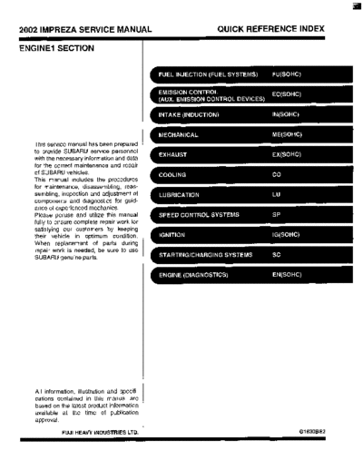
2002 IMPREZA SERVICE MANUAL QUICK REFERENCE INDEX
ENGINE1 SECTION
This service manual has been prepared
to provide SUBARU service personnel
with the necessary information and data
for the correct maintenance and repair
of SUBARU vehicles.
This manual includes the procedures
for maintenance, disassembling, reas-
sembling, inspection and adjustment of
components and diagnostics for guid-
ance of experienced mechanics.
Please peruse and utilize this manual
fully to ensure complete repair work for
satisfying our customers by keeping
their vehicle in optimum condition.
When replacement of parts during
repair work is needed, be sure to use
SUBARU genuine parts.
All information, illustration and specifi-
cations contained in this manual are
based on the latest product information
available at the time of publication
approval.
FUJI HEAVY INDUSTRIES LTD. G1830BE2
FUEL INJECTION (FUEL SYSTEMS)
FU(S0HC)r
Page
1. General Description .................................................................................... 2
2. Throttle Body ............................................................................................. 14
3. Intake Manifold.......................................................................................... 15
4. Engine Coolant Temperature Sensor ........................................................ 27
5. Crankshaft Position Sensor ....................................................................... 28
6. Camshaft Position Sensor ......................................................................... 29
7. Knock Sensor ............................................................................................ 30
8. Throttle Position Sensor ............................................................................ 31
9. Intake Air Temperature and Pressure Sensor ........................................... 34
10. Atmospheric Pressure Sensor .................................................................. 35
11. Idle Air Control Solenoid Valve ................................................................. 36
12. Air Assist Injector Solenoid Valve ............................................................. 37
13. Fuel Injector .............................................................................................. 38
14. Front Oxygen (NF) Sensor ....................................................................... 43
15. Rear Oxygen Sensor ................................................................................. 45
16. Engine Control Module.............................................................................. 47
17. Main Relay ................................................................................................ 48
18. Fuel Pump Relay....................................................................................... 49
19. Fuel ........................................................................................................... 50
20 . Fuel Tank .................................................................................................. 51
21 . Fuel Filler Pipe .......................................................................................... 54
22 . Fuel Pump ................................................................................................. 59
23 . Fuel Level Sensor ..................................................................................... 62
24. Fuel Sub Level Sensor .............................................................................. 63
25 . Fuel Filter .................................................................................................. 65
26 . Fuel Cut Valve ........................................................................................... 66
27. Fuel Damper Valve ................................................................................... 67
28 . Fuel Delivery, Return and Evaporation Lines ............................................ 68
29 . Fuel System Trouble in General ............................................................... 71
GENERAL DESCRIPTION
FUEL INJECTION (FUEL SYSTEMS)
Fuel tank
I Capacity I 60 8 (15.9 US aal, 13.2 Imp aal) I
I Location I Under rear seat I
Type Impeller
Shutoff discharge pressure 370 - 677 kPa (3.77 - 6.9 kg/cm2, 53.6 - 98 psi)
Fuel pump
More than 65 9 (17.2 US gal, 14.3 Imp gal)/h
Discharge flow
I12 V at 300 kPa (3.06 kn/cm2,43.5 usi)l
Fuel filter I Cartridge type I
FU(S0HC)-2
GENERAL DESCRIPTION
FUEL INJECTION (FUEL SYSTEMS)
FU(SOHC)9
GENERAL DESCRIPTION
FUEL INJECTION (FUEL SYSTEMS)
B: COMPONENT
1. INTAKE MANIFOLD
EN1172
FU(S0HC)-4
GENERAL DESCRIPTION
FUEL INJECTION (FUEL SYSTEMS)
Intake manifold gasket O-ring (28) Accelerator cable bracket
Fuel injector pipe RH Plug cord holder LH
Fuel injector Fuel pipe protector RH Tightening torque: N.m (kgf-m, ft-lb)
O-ring Fuel pipe ASSY T1: 3.4 (0.35,2.5)
O-ring Fuel hose T2: 4.9 (0.5, 3.6)
O-ring Clip T3: 6.4 (0.65, 4.7)
Plug Clip T4: lg(1.9, 13.7)
PCV valve Air assist injector solenoid valve T5: 16 (1.6, 11.8)
Purge control solenoid valve Air assist injector solenoid valve T6: 25 (2.5, 18.1)
Nipple bracket T7: 7.35 (0.75, 5.42)
Intake manifold Guide pin T8: 17f1.7, 12.5)
Fuel injector pipe LH Atmospheric pressure sensor T9: l.S(O.15, 1.1)
Fuel pipe protector LH bracket
Intake air temperature and pres- Atmospheric pressure sensor
sure sensor Plug cord holder RH
FU(S0HC)-5
GENERAL DESCRIPTION
FUEL INJECTION(FUEL SYSTEMS)
2. AIR INTAKE SYSTEM
1;
;1
B2M3455C
(1) Gasket (4) Throttle body Tightening torque: N.m (kgf-m, ft-lb)
(2) Throttle position sensor T l : l.S(O.16, 1.2)
(3) Idle air control solenoid valve T2: 22 (2.2, 15.9)
FU(S0HC)-6
GENERAL DESCRIPTION
FUEL INJECTION (FUEL SYSTEMS)
3. CRANKSHAFT POSITION, CAMSHAFT
POSITION AND KNOCK SENSORS
I
(1) Crankshaft position sensor (4) Camshaft position sensor support Tightening torque: N-m (kgf-m, ft-lb)
(2) Knock sensor T1: 6.4 (0.65, 4.7)
(3) Camshaft position sensor T2: 24 (2.4, 17.4)
FU(S0HC)-7
GENERAL DESCRIPTION
FUEL INJECTION (FUEL SYSTEMS)
4. FUELTANK
EN1119
FU(S0HC)-8
GENERAL DESCRIPTION
FUEL INJECTION [FUEL SYSTEMS)
Heat shield cover Evaporation hose C (29) Fuel sub level sensor gasket
Fuel tank band Evaporation hose 3 (30) Jet pump filter
Protector LH Evaporation hose D (31) Fuel sub level sensor
Protector RH Evaporation hose E (32) Protector cover
Fuel tank Evaporation pipe ASSY (33) Vent valve hose
Canister hose A Retainer (34) Vent valve
Clamp Quick connector (35) Fuel tank pressure sensor
Fuel pump gasket Jet pump hose A (36) Fuel tank pressure sensor hose
Fuel pump ASSY Fuel return hose A (37) Vent valve gasket
Fuel cut valve gasket Fuel pipe ASSY
Fuel cut valve Jet pump hose 3 Tightening torque: N-m (kgf-m, ft-lb)
Evaporation hose A Fuel return hose B T I : 4.4 (0.45, 3.3)
Clip Evaporation hose F T2: 7.4 (0.75, 5.4)
Joint pipe Evaporation hose G T3: 33 (3.4,25)
FU(S0HC)-9
GENERAL DESCRIPTION
FUEL INJECTION(FUEL SYSTEMS)
5. FUELLINE
EN1120
FU(S0HC)-10
GENERAL DESCRIPTION
FUEL INJECTION (FUEL SYSTEMS)
Clip Evaporation hose J (25) Canister holder
Fuel delivery hose A Evaporation hose K (26) Evaporation hose L
Fuel filter bracket Joint pipe (27) Pressure control solenoid valve
Fuel filter holder Canister hose A (28) Canister hose B
Fuel filter cup Air filter hose A (29) Canister
Fuel filter Drain valve hose (30) Fuel pipe ASSY
Evaporation hose Air filter hose B
Clip Drain filter
Fuel delivery hose B Drain valve Tightening torque: N-m (kgf-m, ft-lb)
Fuel return hose A Canister upper bracket T1: 25(2.5, 18.1)
Fuel return hose 6 Cushion rubber T2: 23 (2.3, 16.6)
Fuel damper Canister lower bracket T3: 1.25 (0.13, 0.94)
FU(S0HC)-11
GENERAL DESCRIPTION
FUEL INJECTION (FUEL SYSTEMS)
6. FUEL FILLER PIPE
EN1121
Fuel filter pipe ASSY (9) Filler ring Tightening forque: N.m (kgf-m, ft-lb)
Evaporation hose holder (10) Filler cap T1: 4.4 (0.45, 3.3)
Clamp (1 1) Shut valve T2: 7.5 (0.76, 5.53)
Clamp (12) Evaporation hose B
Evaporation hose A (1 3) Evaporation hose C
Evaporation pipe (14) Joint pipe
Evaporation pipe holder (15) Fuel filler pipe protector
Filler pipe packing
FU(S0HC)-12
GENERAL DESCRIPTION
FUEL INJECTION (FUEL SYSTEMS)
C: CAUTION Be careful not to burn your hands, because each
0 Wear working clothing, including a cap, protec- is
part On the vehicle hot after running.
tive goggles, and protective shoes during opera- Be sure to tighten fasteners including bolts and
tion. nuts to the specified torque.
0 Remove contamination including dirt and corro- Place shop jacks or safety stands at the specified
sion before removal, installation or disassembly. points.
0 Keep the disassembled parts in order and pro- Before disconnecting electrical connectors of
tect them from dust or dirt. sensors or units, be sure to disconnect negative
Before removal, installation or disassembly, be terminal from
sure to clarify the failure. Avoid unnecessary re- 0 Place "NO F I R E signs near the working area.
moval, installation, disassembly, and replacement. o Be careful not to Spill fuel on the floor-
D: PREPARATION TOOL
ILLUSTRATION TOOL NUMBER DESCRlPTlON REMARKS
24082AA150 ZARTRIDGE
Newly adopted
001)
82M3076 Troubleshootingfor electrical system.
22771AA030 SELECT MONI- Troubleshooting for electrical systems.
TOR KIT English: 22771AA030 (Without printer)
German: 22771AA070 (Without printer)
French: 22771AA080 (Without printer)
Spanish: 22771AA090 (Without printer)
I
FU(S0HC)-13
THROTTLE BODY
FUEL INJECTION (FUEL SYSTEMS)
2. Throttle Body 7) Disconnect the engine coolant hoses from the
throttle body.
A: REMOVAL
1) Disconnect the battery ground cable.
8) Remove the bolts which install throttle body to
the intake manifold.
2) Remove the air cleaner case.
B: INSTALLATION
3) Disconnect the accelerator cable (A). Install in the reverse order of removal.
4) Disconnect the cruise control cable (B). (With NOTE:
cruise control model) Always use a new gasket.
Tightening torque:
Throttle body;
22 N-m (2.2 kgf-m, 15.9 ft-lb)
5) Disconnect the connectors from the idle air con-
trol solenoid valve and throttle position sensor.
6) Disconnect the air by-pass hose from the throttle
body.
I
B2M3457A
(A) Throttle position sensor
(B) Idle air control solenoid valve
(C) Air by-pass hose from air assist injector sole-
noid valve
FU(S0HC)-14
INTAKE MANIFOLD
FUEL INJECTION (FUEL SYSTEMS)
(3) Remove the bolts which hold power steering
3. Intake Manifold pipes onto the intake manifold protector.
A: REMOVAL NOTE:
1) Release the fuel pressure.
2) Open the fuel flap lid, and remove the fuel filler
cap.
3) Disconnect the battery ground cable.
(4) Remove the bolts which install power steer-
ing pump bracket
4) Remove the air intake duct and air cleaner as-
sembly. and
5 ) Disconnect the accelerator cable (A).
6) Disconnect the cruise control cable (B). (With
cruise control model)
(5) Disconnect the connector from the power
steering pump switch.
7) Remove the power steering pump.
(1) Remove the resonator chamber. (6) Remove the power steering tank from the
(2) Remove the front side V-belt.
/t/
EN0361
FU(S0HC)-15
INTAKE MANIFOLD
FUEL INJECTION (FUEL SYSTEMS)
(7) Place the power steering pump on the right 12) Remove the air cleaner case stay RH and en-
side wheel apron. gine harness bracket, and disconnect the engine
harness connectors from the bulkhead harness
connectors.
8) Disconnect the spark plug cords from the spark
plugs.
r . I I 7- - 9 B2M4260
9) Disconnect the PCV hose from the intake mani- 13) Disconnect the connectors from the engine
fold. coolant temperature sensor.
10) Disconnect the engine coolant hose from the 14) Disconnect the knock sensor connector.
throttle body.
15) Disconnect the connector from the crankshaft
11) Disconnect the brake booster hose. position sensor.
FU(S0HC)-16
INTAKE MANIFOLD
FUEL INJECTION (FUEL SYSTEMS)
16) Disconnect the connector from the oil pressure 19) Remove the bolts which hold intake manifold
switch. onto the cylinder heads.
17) Disconnect the connector from the camshaft 20) Remove the intake manifold.
position sensor.
~
B: INSTALLATION
18) Disconnect the fuel hoses from the fuel pipes. 1) Install the intake manifold onto the cylinder
WARNING: heads.
Do not spill fuel. NOTE:
Catch fuel from hoses in a container or cloth. Always use new gaskets.
Tightening torque:
25 N-m (2.5 kgf-m, 18.1 fi-lb)
(A) Fuel delivery hose
(B) Return hose
(C) Evaporation hose
FU(S0HC)-17
INTAKE MANIFOLD
FUEL INJECTION (FUEL SYSTEMS)
2) Connect the fuel hoses. 6) Connect the knock sensor connector
7) Connect the connectors to the engine coolant
(A) Fuel delivery hose
temperature sensor.
(B) Return hose
(C) Evaporation hose
3) Connect the connector to the camshaft position
sensor.
8) Install the air cleaner case stay RH and engine
harness bracket, and connect the engine harness
connectors to the bulkhead connectors.
4) Connect the connector to the oil pressure switch.
9) Connect the brake booster hose.
5) Connect the connector to the crankshaft position
sensor.
--
.-
FU(S0HC)-18
I INTAKE MANIFOLD
FUEL INJECTION (FUEL SYSTEMS)
10) Connect the engine coolant hose to the throttle (3) Tighten the bolts which install power steer-
body. ing pump bracket.
Tightening torque:
22 N.m (2.2 kgf-m, 15.9 ft-16)
11) Connect the PCV hose to the intake manifold.
(4) Install the power steering pipes onto the
right side intake manifold protector.
12) Connect the spark plug cords to the spark
plugs.
13) Install the power steering pump.
(1) Install the power steering tank on the brack- (5) Install the front side V-belt.
1
(6) Install the resonator chamber.
Tightening torque:
33 N.m (3.4 kgf-m, 24.6 ft-16)
I
EN0361
(2) Connect the connector to the power steering
pump switch.
14) Connect the accelerator cable (A).
FU(S0HC)-19
INTAKE MANIFOLD
FUEL INJECTION (FUEL SYSTEMS)
15) Connect the cruise control cable (B). (With C: DISASSEMBLY
cruise control models) 1) Disconnect the engine ground terminal from the
intake manifold.
16) Install the air intake duct and air cleaner as-
sembly. and
17) Connect the connector to the fuel pump relay.
--.
R7M3477
EN0344 3) Remove the ignition coil and ignitor assembly.
18) Connect the battery ground cable.
82M3473
4) Remove the intake air temperature and pressure
sensor from the intake manifold.
5 ) Remove the throttle body.
6) Remove the air assist injector solenoid valve
from the intake manifold.
FU(S0HC)-PO
INTAKE MANIFOLD
FUEL INJECTION (FUEL SYSTEMS)
7) Disconnect the pressure regulator vacuum hose 11) Disconnect the connector from the purge con-
from the intake manifold. trol solenoid valve.
I/ H2M2961 02M3485
8) Remove the fuel pipe protector LH. 12) Disconnect the air by-pass hose from the purge
control solenoid valve.
13) Remove the harness bands (A) and harness
bracket (B) which hold engine harness onto the in-
take manifold.
9) Remove the fuel pipe protector RH.
02M4271P
14) Remove the engine harness from the intake
manifold.
15) Remove the purge control solenoid valve.
02M4130
IO) Disconnect the connectors from the fuel injec-
tors.
02M3487
02M4270
FU(S0HC)-21
INTAKE MANIFOLD
FUEL INJECTION (FUEL SYSTEMS)
16) Remove the bolt which installs injector pipe on (2) Remove the fuel injector while lifting up the
the intake manifold as shown in figure. fuel injector pipe.
H2M2970
17) Remove the bolt which installs injector pipe on 20) Disconnect the air by-pass hoses from the in-
the intake manifold. take manifold.
LH side
I RH side
B2M4149A
18) Remove the two bolts which hold fuel pipes on 21) Loosen the clamp which holds the front left side
the left side of intake manifold. fuel hose to the injector pipe and remove the pipe.
19) Remove the fuel injectors. 22) Loosen the clamp which holds the front right
(1) Remove the fuel injector securing clip. side fuel hose to the injector pipe and remove the
pipe.
82M4274
FU(S0HC)-22
INTAKE MANIFOLD
FUEL INJECTION (FUEL SYSTEMS)
23) Remove the fuel injector pipe. 3) Connect the right side fuel hose to the injector
pipe, and tighten the clamp screw.
H2M2975
~
B2M4274
24) Remove the bolt which installs the fuel pipes on
the intake manifold. 4) Install the fuel injector pipe.
B2M349 1 H2M297E
25) Remove the fuel pipe assembly and pressure 5 ) Connect the left side fuel hose to the injector
regulator, from the intake manifold. pipe, and tighten the clamp screw.
D: ASSEMBLY
1) Install the fuel pipe assembly and pressure reg-
ulator, etc. to the intake manifold.
2) Tighten the bolt which installs the fuel pipes on
the intake manifold.
Tightening torque:
4.9 N-m (0.5 kgf-m, 3.6 ff-lb)
~
6) Connect the air assist hoses.
LH side
I RH side
B2M3491
B2M4149A
FU(SO HC)-23
INTAKE MANIFOLD
FUEL INJECTION (FUEL SYSTEMS)
7 ) Install the fuel injectors. Tightening torque:
NOTE: 19 N.m (1.9 kgf-m, 13.7 ft-lb)
Always use new O-rings.
9) Tighten the two bolts which install the fuel pipes
on the left side of intake manifold.
(A) O-ring
(B) Fuel injector
Tightening torque:
4.9 N-m (0.5 kgf-m, 3.6 ft-lb)
NOTE:
Do not forget to install the fuel injector securing clip.
I 10) Tighten the bolt which install the injector pipe
B2M3488 on the intake manifold.
8) Tighten the bolt which installs the injector pipe Tightening torque:
on the intake manifold. 4.9 N-m (0.5 kgf-m, 3.6 ft-lb)
Tightening torque:
4.9 N-m (0.5 kgf-m, 3.6 ft-lb)
FU(S0HC)-24
INTAKE MANIFOLD
FUEL INJECTION (FUEL SYSTEMS)
11) Install the purge control solenoid valve. 16) Install the fuel pipe protector RH.
Tightening torque: Tightening torque:
16 N-m (1.6 kgf-m, 11.8 ff-lb) 19 N.m (1.9 kgf-m, 13.7 ff-lb)
\\ n
02M3487 B2M4130
12) Connect the hoses to the purge control sole- 17) Install the fuel pipe protector LH.
noid valve. Tightening torque:
CAUTION: 19 N-m (1.9 kgf-m, 13.7 ff-lb)
Carefully connect the evaporation hoses.
To fuel +
+To intakc
Pipe
manifold
I
B2M1893P
18) Connect the pressure regulator vacuum hose
13) install the engine harness onto the intake man- to the intake manifold.
ifold.
14) Connect the connectors to the fuel injectors
and purge control solenoid valve.
15) Hold the engine harness by harness band (A)
and harness bracket (9).
Tightening torque:
16 N-m (1.6 kgf-m, 11.8 ff-lb)
// H2M2961
19) install the air assist injector solenoid valve to
the bracket.
20) Install the throttle body to the intake mani-
fold.
I EN11731 21) Install the intake air temperature and pressure
sensor.
Do not use harness band on harnesses where they 22) Connect the connector to the intake air temper-
are supposed to be protected by the fuel pipe pro- ature and pressure sensor.
tector.
FU(S0HC)-25
INTAKE MANIFOLD
FUEL INJECTION (FUEL SYSTEMS)
23) Install the ignition coil and ignitor assembly.
I 82M3473
24) Connect the connector to the ignition coil and
ignitor assembly.
25) Install the engine ground terminal to the intake
manifold.
Tightening torque:
79 " (7.9 kgf-m, 73.7 ft-lb)
I
E: INSPECTION
Make sure the fuel pipe and fuel hoses are not
cracked and that connections are tight.
FU(S0HC)-26
ENGINE COOLANT TEMPERATURE SENSOR
FUEL INJECTION (FUEL SYSTEMS)
4. Engine Coolant Temperature B: INSTALLATION
Install in the reverse order of removal.
Sensor
Tightening torque:
A: REMOVAL 18 N-m (1.8 kgf-m, 13.3 ft-lb)
1) Disconnect the battery ground cable.
2) Remove the air intake duct and air cleaner as-
sembly. and
3) Disconnect the connector from the engine cool-
ant temperature sensor.
v
4) Remove the engine coolant temperature sensor.
FU(SOHC)-27
a
CRANKSHAFT POSITION SENSOR
FUEL INJECTION (FUEL SYSTEMS)
5. Crankshaft Position Sensor B: INSTALLATION
Install in the reverse order of removal.
A: REMOVAL
1) Disconnect the battery ground cable. Tightening torque:
T: 6.4 N.m (0.65 kgf-m, 4.7 ft-lb)
2) Remove the bolt which install crankshaft position
sensor to the cylinder block.
3) Remove the crankshaft position sensor, and dis-
connect the connector from it.
FU(S0HC)-28
CAMSHAFT POSITION SENSOR
FUEL INJECTION (FUEL SYSTEMS)
6. Camshaft Position Sensor 5) Remove the camshaft position sensor and cam-
shaft position sensor support as a unit.
A: REMOVAL 6) Remove the camshaft position sensor itself.
1) Disconnect the battery ground cable.
2) Disconnect the connector from the camshaft po-
sition sensor.
8
B: INSTALLATION
Install in the reverse order of removal.
Tightening torque:
Camshaft position sensor support;
6.4 N.m (0.65 kgf-m, 4.7 ff-lb)
B2M2322
Camshaft position sensor;
6.4 N-m (0.65 kgf-m, 4.7 ft-lb)
3) Remove the bolt which installs camshaft position
sensor to the camshaft position sensor support.
4) Remove the bolt which installs camshaft position
sensor support to the camshaft cap LH.
\' 02M2321 I
FU(S0HC)-29
I
KNOCK SENSOR
FUEL INJECTION (FUEL SYSTEMS)
7. Knock Sensor B: INSTALLATION
1) Install the knock sensor to the cylinder block.
A: REMOVAL
1) Disconnect the battery ground cable from the Tightening torques
battery ground terminal. 24 N-m (2.4 kgf-m, 17.4 fi-lb)
NOTE:
The extraction area of the knock sensor cord must
be positioned at a 60" angle relative to the engine
rear.
2) Remove the air cleaner case.
3) Disconnect the knock sensor connector.
(A) Front side
2) Connect the knock sensor connector.
4) Remove the knock sensor from the cylinder
block.
3) Install the air cleaner case.
4) Connect the battery ground cable.
FU(S0HC)-30
THROTTLE POSITION SENSOR
FUEL INJECTION (FUEL SYSTEMS)
8. Throttle Position Sensor B: INSTALLATION
Install in the reverse order of removal.
A: REMOVAL
1) Disconnect the battery ground cable.
Tightening torque:
1.6 N.m (0.16 kgf-m, 1.2 W b )
CAUTION:
When installing throttle position sensor, adjust
to the specified data.
2) Disconnect the connector from the throttle posi-
tion sensor.
02M3493
3) Remove the throttle position sensor holding
screws, and remove it.
FU(S0HC)Sl
THROTTLE POSITION SENSOR
FUEL INJECTION(FUEL SYSTEMS)
C: ADJUSTMENT 4) When using Subaru Select Monitor;
1) Turn the ignition switch to OFF. (1) Turn the ignition switch to OFF.
2) Loosen the throttle position sensor holding (2) Loosen the throttle position sensor holding
screws. screws.
02M3765 02M3765
3) When using voltage meter; NOTE:
(1) Take out the ECM. For detailed operation procedures, refer to the Sub-
(2) Turn the ignition switch to ON. aru Select Monitor Operation Manual.
(3) Adjust the throttle position sensor to the (3) Insert the cartridge to the Subaru Select
proper position to allow the voltage signal to the Monitor.
ECM to be in specification.
Connector & terminal / Specified voltage
(8136) NO. 15 - (B136) NO. 17/0.45 - 0.55 V
[Fully closed.]
-
76" n3 2 1
(4) Connect the Subaru Select Monitor to the
data link connector.
02M4131A
(4) Tighten the throttle position sensor holding
screws.
Tightening torque:
1.6 Nom(0.16 kgf-m, 1.2 ff-lb)
5 ) Turn the ignition switch to ON, and the Subaru
Select Monitor switch to ON.
6) Select the {2. Each System Check} in Main
Menu.
7) Select the {Engine Control System} in Selection
Menu.
02M376E
8) Select the 11. Current Data Display & Save} in
Engine Control System Diagnosis.
9) Select the (1.12 Data Display} in Data Display
Menu.
FU(S0HC)-32
THROTTLE POSITION SENSOR
FUEL INJECTION (FUEL SYSTEMS)
10) Adjust the throttle position sensor to the proper
position to match with the following specifications.
Condition: Throttle fully closed
Throttle opening angle 0.00%
Throttlesensor voltage 0.50 V
11) Tighten the throttle position sensor holding
screws.
Tightening torque:
1.6 N.m (0.16 kgf-m, 1.2 ft-16)
FU(S0HC)-33
INTAKE AIR TEMPERATURE AND PRESSURE SENSOR
FUEL INJECTION (FUEL SYSTEMS)
9. Intake Air Temperature and B: INSTALLATION
Pressure Sensor Install in the reverse order of removal.
Tightening torque:
A: REMOVAL 3.4 N.m ( . 5kgf-m, 2.5 ff-lb)
03
1) Disconnect the battery ground cable.
I B2M3497
NOTE:
2) Disconnect the spark plug cord from the ignition
Replace O-ring with new one.
coil and ignitor assembly.
B2M3495
0 H2M2999
3) Disconnect the connector from the intake air
temperature and pressure sensor.
4) Remove the intake air temperature and pressure
sensor.
FU(S0HC)-34
ATMOSPHERIC PRESSURE SENSOR
FUEL INJECTION (FUEL SYSTEMS)
1O.Atmospheric Pressure Sen- B: INSTALLATION
Install in the reverse order of removal.
sor
Tightening torque:
A: REMOVAL 6.4 N.m (0.65 kgf-m, 4.7 ff-lb)
1) Disconnect the battery ground cable.
/
EN1001
2) Disconnect the connector from the atmospheric
pressure sensor.
3) Remove the atmospheric pressure sensor from
the bracket.
I EN1001
FU(S0HC)-35
IDLE AIR CONTROL SOLENOID VALVE
FUEL INJECTION (FUEL SYSTEMS)
11.Idle Air Control Solenoid B: INSTALLATION
Valve Install in the reverse order of removal.
NOTE:
A: REMOVAL Always use new gasket.
1) Disconnect the battery ground cable.
Tightening torque:
7.6 N*m (0.76 kgf-m, 7.2 fWb)
2) Disconnect the connector from the idle air con-
trol solenoid valve.
I
3) Remove the idle air control solenoid valve from
the throttle body.
FU(S0HC)-36
AIR ASSIST INJECTOR SOLENOID VALVE
FUEL INJECTION (FUEL SYSTEMS)
12.Air Assist Injector Solenoid 9: INSTALLATION
Install in the reverse order of removal.
Valve
Tightening torque:
A: REMOVAL 6.4 N-m (0.65 kgf-m, 4.7 ff-lb)
1) Disconnect the battery ground cable.
B2M350:
2) Disconnect the connector from the air assist in-
jector solenoid valve and disconnect the air by-
pass hoses.
3) Remove the air assist injector solenoid valve
from the intake manifold.
B2M3.50:
FU(S0HC)-37
FUEL INJECTOR
FUEL INJECTION (FUEL SYSTEMS)
13.Fuel Injector 6) Remove the power steering pump and tank from
the brackets.
A: REMOVAL (1) Remove the front side V-belt.
1. RH SIDE (2) Remove the bolts which hold the power
1) Release the fuel pressure. steering pipes onto the intake manifold protec-
2) Open the fuel flap lid, and remove the fuel filler
cap.
3) Disconnect the battery ground cable.
(3) Remove the bolts which install the power
steering pump to the bracket.
4) Remove the resonator chamber.
5 ) Remove the spark plug cords from the spark
plugs (#1 and #3 cylinders).
(4) Disconnect the connector from the power
steering pump switch.
FU(S0HC)-38
I FUEL INJECTOR
FUEL INJECTION (FUEL SYSTEMS)
(5) Remove the power steering tank from the 9) Remove the bolt which holds the injector pipe to
bracket by pulling it upwards. the intake manifold.
(6) Place the power steering pump and tank on
the right side wheel apron.
' I 02M4282
10) Remove the fuel injector from the intake mani-
fold.
7) Remove the fuel pipe protector RH. (1) Remove the fuel injector securing clip.
B2M4130
8) Disconnect the connector from fuel injector. (2) Remove the fuel injector while lifting up the
fuel injector pipe.
I
FU(SOHC)S9
FUEL INJECTOR
FUEL INJECTION (FUEL SYSTEMS)
2. LH SIDE 8 ) Move the washer tank, and secure it away from
the working area.
1) Release the fuel pressure.
2) Open the fuel flap lid, and remove the fuel filler
cap.
3) Disconnect the battery ground cable.
9) Remove the spark plug cords from the spark
plugs (#2 and #4 cylinders).
4) Remove the two bolts which install the washer
tank on the body.
10) Remove the fuel pipe protector LH.
5) Disconnect the connector from the front window
washer motor.
6) Disconnect the connector from the rear gate
glass washer motor.
11) Disconnect the connector from the fuel injector.
7) Disconnect the rear window glass washer hose
from the washer motor, then plug the connection
with a suitable cap.
FU(S0HC)-40
FUEL INJECTOR
FUEL INJECTION (FUEL SYSTEMS)
12) Remove the bolt which holds the injector pipe (2) Remove the fuel injector while lifting up the
to the intake manifold. fuel injector pipe.
B: INSTALLATION
1. RH SIDE
Install in the reverse order of removal.
CAUTION:
Replace O-rings with new ones.
13) Remove the bolt which holds the fuel pipe on
the left side intake manifold.
(A) O-ring
(B) Fuel injector
Tightening torque:
4.9 N.m (0.5 kgf-m, 3.6 ff-lb)
14) Remove the fuel injector from the intake mani-
fold.
(1) Remove the fuel injector securing clip.
FU(SOHC)-41
FUEL INJECTOR
FUEL INJECTION (FUEL SYSTEMS)
Tightening torque: Tightening torque:
19 N.m (1.9 kgf-m, 13.7 ft-lb) 4.9 Nom(0.5 kgf-m, 3.6 ft-lb)
Tightening torque: Tightening torque:
19 N-m (1.9 kgf-m, 73.7 ft-lb) 4.9 N-m (0.5 kgf-m, 3.6 ft-lb)
I B2M4130
2. LH SIDE Tightening torque:
Install in the reverse order of removal. 19 Nom(1.9 kgf-m, 13.7 ft-lb)
CAUTION:
Replace O-rings with new ones.
Tightening torque:
19 N.m (7.9 kgf-m, 13.7 ft-lb)
(A) O-ring
(B) Fuel injector
FU(S0HC)-42
FRONT OXYGEN (NF) SENSOR
FUEL INJECTION (FUEL SYSTEMS)
14.Front Oxygen (NF) Sensor B: INSTALLATION
1) Before installing front oxygen (NF)sensor, apply
A: REMOVAL the anti-seize compound only to the threaded por-
1) Disconnect the battery ground cable. tion of front oxygen (NF)sensor to make the next
removal easier.
An ti-seize compound:
SS-30 by JET LUBE
CAUTION:
Never apply anti-seize compound to protector
of front oxygen (NF)sensor.
I
2) Disconnect the connector from the front oxygen
(NF)sensor.
I
2) Install the front oxygen (NF)sensor.
Tightening torque:
21 N.m (2.7 kgf-m, 15.2 ff-lb)
I I
3) Lift-up the vehicle.
4) Apply SUBARU CRC or its equivalent to the
threaded portion of front oxygen (NF)sensor, and
leave it for one minute or more.
SUBARU CRC (Part No. 004301003)
5) Remove the front oxygen (NF)sensor.
CAUTION:
When removing the oxygen (NF)sensor, wait iwer the vehicle.
until exhaust pipe cools, otherwise it will dam-
4) Connect the connector of front oxygen (NF)sen-
age exhaust pipe.
sor.
FU(S0HC)-43
FRONT OXYGEN (NF) SENSOR
a
FUEL INJECTION (FUEL SYSTEMS)
5 ) Connect the battery ground cable.
FU(S0HC)-44
REAR OXYGEN SENSOR
81
FUEL INJECTION (FUEL SYSTEMS)
15.Rear Oxygen Sensor B: INSTALLATION
1) Before installing rear oxygen sensor, apply the
A: REMOVAL anti-seize compound only to the threaded portion of
1) Disconnect the battery ground cable. rear oxygen sensor to make the next removal eas-
ier.
CAUTION:
Never apply anti-seize compound to protector
of rear oxygen sensor.
Anti-seize compound:
SS-30 by JET LUBE
I
2) Lift-up the vehicle.
3) Disconnect the connector from the rear oxygen
sensor.
R7M0742A
2) Install the rear oxygen sensor.
Tightening torque:
2 N.m (2.7 kgf-m, 75.2 ft-lb)
7
4) Apply SUBARU CRC or its equivalent to the
threaded portion of rear oxygen sensor, and leave
it for one minute or more.
SUBARU CRC (Part No. 004307003)
5 ) Remove the rear oxygen sensor.
CAUTION:
When removing the oxygen sensor, wait until 3) Connect the connector to the rear oxygen sen-
exhaust pipe cools, otherwise it will damage ex- sor.
haust pipe.
__ .
4) Lower the vehicle.
FU(S0HC)-45
REAR OXYGEN SENSOR
FUEL INJECTION (FUEL SYSTEMS)
5) Connect the battery ground cable.
FU(S0HC)-46
ENGINE CONTROL MODULE
FUEL INJECTION (FUEL SYSTEMS)
16.Engine Control Module B: INSTALLATION
Install in the reverse order of removal.
A: REMOVAL CAUTION:
1) Disconnect the battery ground cable. When replacing ECM, be careful not to use the
wrong spec. ECM to avoid any damage to the
fuel injection system.
Tightening torque:
50 Nom(0.51 kgf-m, 3.7 ff-lb)
2) Remove the lower inner trim of passenger side.
3) Detach the floor mat of front passenger seat.
4) Remove the protect cover.
I EN118t
5) Remove the nuts (A) which hold ECM to the
bracket.
6) Remove the clip (B) from the bracket.
186
7) Disconnect the ECM connectors and take out
the ECM.
FU(S0HC)-47
MAIN RELAY
FUEL INJECTION (FUEL SYSTEMS)
17.Main Relay B: INSTALLATION
Install in the reverse order of removal.
A: REMOVAL
1 ) Disconnect the battery ground cable.
2) Remove the passenger's side front side sill cov-
er.
3) Remove the bolt which holds main bracket on
the body.
4) Disconnect the connectors from the main relay.
FU(S0HC)-48
FUEL PUMP RELAY
FUEL INJECTION (FUEL SYSTEMS)
18.Fuel Pump Relay B: INSTALLATION ~
Install in the reverse order of removal.
A: REMOVAL
1) Disconnect the battery ground cable.
2) Remove the passenger's side front side sill cov-
er.
3) Remove the bolt which holds fuel pump relay
bracket on the body.
4) Disconnect the connector from the fuel pump.
5) Remove the fuel pump relay from the mounting
bracket.
FU(S0HC)-49
FUEL
FUEL INJECTION (FUEL SYSTEMS)
19.Fuel 4) Drain the fuel from the fuel tank.
Set a container under the vehicle and remove the
A: OPERATION drain plug from the fuel tank.
1. RELEASING OF FUEL PRESSURE
WARNING:
Place "NO FIRE" signs near the working area.
Be careful not to spill fuel on the floor.
1) Disconnect the connector from the fuel pump re-
lay.
---. 5) Tighten the fuel drain plug.
Tightening torque:
26 N.m (2.65 kgf-m, 19.2 ft-lb)
EN0344
2) Start the engine and run it until it stalls.
3) After the engine stalls, crank it for five more sec-
onds.
4) Turn the ignition switch to OFF.
2. DRAINING FUEL
WARNING:
Place "NO FIRE" signs near the working area.
Be careful not to spill fuel on the floor.
1) Set the vehicle on the lift.
2) Disconnect the battery ground cable.
3) Lift-up the vehicle.
FU(S0HC)-50
im
FUEL TANK
FUEL INJECTION (FUEL SYSTEMS)
20.Fuel Tank 10) Disconnect the connector from the drain valve.
A: REMOVAL
WARNING:
Place "NO FIRE" signs near the working area.
Be careful not to spill fuel on the floor.
1) Set the vehicle on the lift.
2) Release the fuel pressure.
3) Drain the fuel from the fuel tank. B2M 1743
4) Remove the rear seat.
5) Disconnect the connector (A) of fuel tank cord to 11) Loosen the clamp and disconnect the fuel filler
the rear harness. hose (A) and air vent hose (B) from the fuel filler
6) Push the grommet (B) which holds the fuel tank pipe.
cond on the floor panel into under the body.
S2M0193A
EN0537 12) Move the clips, and disconnect the quick con-
7) Remove the rear crossmember. Delivery, Return and Evaporation Lines.>
8) Move the clamp, and disconnect the evaporation 13) Disconnect the fuel hoses.
hose from the canister.
\ I
S2M0949A
9) Disconnect the connector from the pressure con-
trol solenoid valve.
FU(S0HC)-51
FUEL TANK
FUEL INJECTION (FUEL SYSTEMS)
14) Support the fuel tank with transmission jack, re- 4) Connect the fuel hoses, and hold then with clips
move the bolts from bands and dismount the fuel and quick connector.
A helper is required to perform this work.
5 ) Connect the connector to the drain valve.
B: INSTALLATION
1) Support the fuel tank with transmission jack and
push the fuel tank harness into access hole with
grommet.
2) Set the fuel tank and temporarily tighten the bolts
of fuel tank bands.
WARNING:
A helper is required to perform this work.
I B2M1743
6) Connect the connector to the pressure control
solenoid valve.
7) Connect the evaporation hose to the canister,
◦ Jabse Service Manual Search 2026 ◦ Jabse Pravopis ◦ onTap.bg ◦ Other service manual resources online : Fixya ◦ eServiceinfo