Service Manuals, User Guides, Schematic Diagrams or docs for : . Car Manuals Subaru Impreza 2001-2002.2004-2007 Approved Subaru Impreza 2002 3 - DOHC Engine
<< Back | HomeMost service manuals and schematics are PDF files, so You will need Adobre Acrobat Reader to view : Acrobat Download Some of the files are DjVu format. Readers and resources available here : DjVu Resources
For the compressed files, most common are zip and rar. Please, extract files with Your favorite compression software ( WinZip, WinRAR ... ) before viewing. If a document has multiple parts, You should download all, before extracting.
Good luck. Repair on Your own risk. Make sure You know what You are doing.
Image preview - the first page of the document
>> Download 3 - DOHC Engine documenatation <<
Text preview - extract from the document
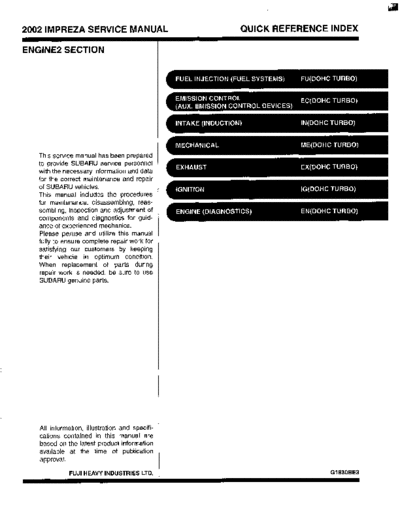
2002 IMPREZA SERVICE MANUAL QUICK REFERENCE INDEX
ENGINE2 SECTION
This service manual has been prepared
to provide SUBARU service personnel
with the necessary information and data
for the correct maintenance and repair
of SUBARU vehicles.
This manual includes the procedures
for maintenance, disassembling, reas-
sembling, inspection and adjustment of
components and diagnostics for guid-
ance of experienced mechanics.
Please peruse and utilize this manual
fully to ensure complete repair work for
satisfying our customers by keeping
their vehicle in optimum condition.
When replacement of parts during
repair work is needed, be sure to use
SUBARU genuine parts.
All information, illustration and specifi-
cations contained in this manual are
based on the latest product information
available at the time of publication
approval.
FUJI HEAVY INDUSTRIES LTD. G1830BE3
FUEL INJECTION (FUEL SYSTEMS)
FU(D0HC TURB0)m
Page
1. General Description .................................................................................... 2
2 . Throttle Body ............................................................................................. 14
3. Intake Manifold .......................................................................................... 15
4 . Engine Coolant Temperature Sensor ........................................................ 29
5. Crankshaft Position Sensor ....................................................................... 30
6 . Camshaft Position Sensor ......................................................................... 31
7 . Knock Sensor ............................................................................................ 32
8. Throttle Position Sensor ............................................................................ 33
9 . Mass Air Flow and Intake Air Temperature Sensor .................................. 34
10. Pressure Sensor ....................................................................................... 35
11. Idle Air Control Solenoid Valve ................................................................. 36
12. Fuel Injector .............................................................................................. 37
13. Tumble Generator Valve Assembly .......................................................... 40
14. Wastegate Control Solenoid Valve ........................................................... 41
15. Front Oxygen (NF) Sensor ....................................................................... 42
16. Rear Oxygen Sensor ................................................................................. 44
17. Exhaust Temperature Sensor ................................................................... 46
18. Engine Control Module.............................................................................. 47
19. Main Relay ................................................................................................ 48
20 . Fuel Pump Relay ....................................................................................... 49
21 . Fuel Pump Controller ................................................................................ 50
22 . Fuel ........................................................................................................... 51
23 . Fuel Tank .................................................................................................. 52
24 . Fuel Filler Pipe .......................................................................................... 55
25 . Fuel Pump ................................................................................................. 60
26 . Fuel Level Sensor ..................................................................................... 62
27 . Fuel Sub Level Sensor .............................................................................. 63
28 . Fuel Filter .................................................................................................. 65
29 . Fuel Cut Valve ........................................................................................... 66
30. Fuel Damper Valve ................................................................................... 67
31 . Fuel Deliverv. Return and Evaporation Lines ............................................
a . 68
32 . Fuel System Trouble in General ............................................................... 71
GENERAL DESCRIPTION
FUEL INJECTION (FUEL SYSTEMS)
1. General Description
A: SPECIFICATIONS
Capacity 60 8 (15.9 US gal, 13.2 Imp gal)
Location Under rear seat
Type Impeller
Shutoff discharge pressure 450 - 677 kPa (4.59 - 6.9 kg/cm2, 65.27 - 98.2 psi)
Fuel pump
More than 130 8 (34.3 US gal, 28.6 Imp gal)/h
Discharge flow
[12 V at 300 kPa (3.06 kg/cm2,43.5 psi)]
Fuel filter Cartridge type
FU(D0HC TURBO)-2
GENERAL DESCRIPTION
FUEL INJECTION (FUEL SYSTEMS)
FU(D0HC TURBO)-3
GENERAL DESCRIPTION
FUEL INJECTION (FUEL SYSTEMS)
B: COMPONENT
1. INTAKE MANIFOLD
EN1135
FU(D0HC TURBO)-4
GENERAL DESCRIPTION
FUEL INJECTION (FUEL SYSTEMS)
Fuel pipe ASSY Accelerator cable bracket (25) Fuel pipe protector LH
Fuel hose Fuel injector (26) Nipple
Clip Insulator
,
Purge control solenoid valve Fuel injector pipe Tightening torque: N.m (kgf-m, ft-lb)
Vacuum hose Pressure regulator T1: 4.9 (0.5, 3.6)
Vacuum control hose Pressure regulator hose T2: 6.4 (0.65, 4.7)
Purge valve Fuel pipe protector RH T3: 8.25 (0.84, 6.1)
Purge hose Blow-by hose stay T4: 16 (1.6, 11.8)
Intake manifold gasket Intake manifold T5: 17(1.73, 12.5)
Guide pin Solenoid valve cover T6: 19 (1.94, 13.7)
Tumble generator valve ASSY Solenoid valve cover stay T7: 25 (2.5, 18.1)
Tumble generator valve gasket Wastegate control solenoid valve
ASSY
FU(D0HC TURB0)-5
GENERAL DESCRIPTION
FUEL INJECTION (FUEL SYSTEMS)
2. AIR INTAKE SYSTEM
EN113
~
(1) Gasket (5) Pressure sensor Tightening torque: N.m (kgf-m, ft-lb)
(2) Throttle position sensor (6) Gasket T1: 1.6 (0.16, 1.2)
(3) Idle air control solenoid valve (7) O-ring T2: 2.8 (0.29, 2.1)
(4) Throttle body T3: 22 (2.2, 15.9)
FU(D0HC TURBO)-6
GENERAL DESCRIPTION
FUEL INJECTION (FUEL SYSTEMS)
3. CRANKSHAFT POSITION, CAMSHAFT POSITION AND KNOCK SENSORS
(1) Crankshaft position sensor (3) Camshaft position sensor Tightening torque: N.m (kgf-m, ft-lb)
(2) Knock sensor T1: 6.4 (0.65, 4.7)
T2: 24 (2.4, 17.4)
FU(D0HC TURBO)-7
GENERAL DESCRIPTION
FUEL INJECTION (FUEL SYSTEMS)
4. FUELTANK
EN1119
FU(D0HC TURBO)-8
I
GENERAL DESCRIPTION
FUEL INJECTION (FUEL SYSTEMS)
Heat shield cover Evaporation hose C Fuel sub level sensor gasket
Fuel tank band Evaporation hose B Jet pump filter
Protector LH Evaporation hose D Fuel sub level sensor
Protector RH Evaporation hose E Protector cover
Fuel tank Evaporation pipe ASSY Vent valve hose
Canister hose A Retainer Vent valve
Clamp Quick connector Fuel tank pressure sensor
Fuel pump gasket Jet pump hose A Fuel tank pressure sensor hose
Fuel pump ASSY Fuel return hose A Vent valve gasket
Fuel cut valve gasket Fuel pipe ASSY
Fuel cut valve Jet pump hose B Tightening torque: N-m (kgf-m, ft-lb)
Evaporation hose A Fuel return hose B T1: 4.4 (0.45, 3.3)
Clip Evaporation hose F T2: 7.4 (0.75, 5.4)
Joint pipe Evaporation hose G T3: 33 (3.4, 25)
FU(D0HC TURBO)-9
GENERAL DESCRIPTION
FUEL INJECTION(FUEL SYSTEMS)
5. FUELLINE
EN1120
FU(D0HC TURBO)-I 0
GENERAL DESCRIPTION
FUEL INJECTION (FUEL SYSTEMS)
Clamp Evaporation hose J (25) Canister holder
Fuel delivery hose A Evaporation hose K (26) Evaporation hose L
Fuel filter bracket Joint pipe (27) Pressure control solenoid valve
Fuel filter holder Canister hose A (28) Canister hose B
Fuel filter cup Air filter hose A (29) Canister
Fuel filter Drain valve hose (30) Fuel pipe ASSY
Evaporation hose Air filter hose B
Clip Drain filter Tightening torque: N-m (kgf-m, ft-lb)
Fuel delivery hose B Drain valve T1: 25 (2.5, 18.1)
Fuel return hose A Canister upper bracket T2: 23 (2.3, 16.6)
Fuel return hose B Cushion rubber T3: 1.25 (0.13, 0.94)
Fuel damper Canister lower bracket
FU(D0HC TURBO)-I 1
GENERAL DESCRIPTION
FUEL INJECTION (FUEL SYSTEMS)
6. FUEL FILLER PIPE
EN1121
(1) Fuel filter pipe ASSY (8) Filler pipe packing (15) Fuel filler pipe protector
(2) Evaporation hose holder (9) Filler ring
-
(3) Clamp (10) Filler cap Tightening torque: N.m (kgf-m, ft-lb)
(4) Clamp (11) Shut valve T1: 4.4 (0.45, 3.3)
(5) Evaporation hose A (12) Evaporation hose 6 T2: 7.5 (0.76, 5.5)
(6) Evaporation pipe (13) Evaporation hose C
(7) Evaporation pipe holder (14) Joint pipe
FU(D0HC TURBO)-I 2
GENERAL DESCRIPTION
FUEL INJECTION (FUEL SYSTEMS)
C: CAUTION Be careful not to burn your hands, because each
Wear working clothing, including a cap, protec- part On the vehicle hot after running.
is
tive goggles, and protective shoes during opera- Be sure to tighten fasteners including bolts and
.
tion.
Remove contamination including dirt and corro-
nuts to the specified torque.
Place shop jacks or Safety stands at the specified
.
sion before removal, installation or disassembly.
Keep the disassembled parts in order and pro-
tect them from dust or dirt.
points.
Before disconnecting electrical COntleCtOrS Of
sensors or units, be sure to disconnect negative
Before removal, installation or disassembly, be from
terminal battery.
sure to clarify the failure. Avoid unnecessary re- Place "NO FIRE" signs near the working area.
moval, installation, disassembly, and replacement. Be careful not to Spill fuel on the floor-
D: PREPARATION TOOL
ILLUSTRATION TOOL NUMBER DESCRIPTION REMARKS
24082AA150 CARTRIDGE Troubleshooting for electrical system.
(Newly adopted
tool)
B2M3876
22771AA030 SELECT MONI- Troubleshooting for electrical systems.
TOR KIT English: 22771AA030 (Without printer)
German: 22771AA070 (Without printer)
French: 22771AA080 (Without printer)
Spanish: 22771AA090 (Without printer)
FU(D0HC TURBO)-13
THROTTLE BODY
FUEL INJECTION (FUEL SYSTEMS)
2. Throttle Body 5) Disconnect the engine coolant hoses from the
throttle body.
A: REMOVAL
1) Disconnect the battery ground cable.
6) Remove the bolts which secure the throttle body
to intake manifold.
2) Remove the intercooler.
6: INSTALLATION
3) Disconnect the connector from the throttle posi- Install in the reverse order of removal.
tion sensor (A) and idle air cotrol solenoid valve (B) NOTE:
and pressure sensor (C). Always use a new gasket.
Tightening torque:
22 N-m (2.2 kgf-m, 15.9 M b )
4) Disconnect the accelerator cable.
// EN0785
FU(D0HC TURBO)-14
a
INTAKE MANIFOLD
FUEL INJECTION (FUEL SYSTEMS)
11) Remove the power steering pump.
3. Intake Manifold (1) Remove the front side V-belt.
A: REMOVAL
TURBO)-51, RELEASING OF FUEL PRESSURE, (2) Disconnect the power steering switch con-
OPERATION, Fuel.> nector.
2) Disconnect the battery ground cable.
(3) Remove the bolts which secure the power
3) Lift up the vehicle. steering pipe brackets to the intake manifold.
4) Remove the under cover. NOTE:
5) Drain the coolant about 3.0 0 (3.2 US qt, 2.6 Do not disconnect the power steering hose.
Imp qt).
(4) Remove the bolts which secure the power
6) Remove the air cleaner upper cover and air in- steering pump bracket.
take boot.
7) Remove the air cleaner element.
8) Remove the intercooler.
9) Disconnect the accelerator cable.
10) Remove the coolant filler tank.
FU(D0HC TURBO)-15
INTAKE MANIFOLD
FUEL INJECTION (FUEL SYSTEMS)
(5) Remove the power steering tank from the 14) Disconnect the brake booster hose.
bracket by pulling it upward.
(6) Place the power steering pump on the right
side wheel apron.
- EN0204
15) Disconnect the pressure hose from the intake
duct.
16) Disconnect the engine harness connectors
12) Disconnect the emission hose from the PCV from the bulkhead harness connectors.
valve.
13) Disconnect the engine coolant hoses from the
throttle body.
FU(D0HC TURBO)-16
INTAKE MANIFOLD
FUEL INJECTION (FUEL SYSTEMS)
17) Disconnect the connectors from the engine 21) Disconnect the engine harness fixed by clip (A)
coolant temperature sensor (A), oil pressure switch from the bracket.
(B) and crankshaft position sensor (C).
\\ I II
(6)
S2M2256A
v . 22) Disconnect the fuel delivery hose, return hose
18) Disconnect the knock sensor connector. and evaporation hose.
WARNING:
Catch the fuel from hoses in a container.
S2M1613
19) Disconnect the connector from the camshaft
position sensor.
23) Remove the bolts which secure the intake man-
ifold to the cylinder heads.
20) Disconnect the connector from the ignition coil.
24) Remove the intake manifold.
EN0854
FU(D0HC TURBO)-17
INTAKE MANIFOLD
FUEL INJECTION (FUEL SYSTEMS)
B: INSTALLATION 4) Connect the connector to the knock sensor.
1) Install the intake manifold onto cylinder heads.
NOTE:
Always use new gaskets.
Tightening torque:
25 N-m (2.5 kgf-m, 18.1 ft-16)
S2M1613
5) Connect the connector to the camshaft position
sensor.
2) Connect the fuel delivery hose, return hose, and
evaporation hose.
6) Connect the connector to the ignition coil.
3) Connect the connector to the oil pressure switch
(B), crankshaft position sensor (C) and engine
coolant temperature sensor (A).
EN0854 I
7) Connect the engine harness with clip (A) to the
bracket.
FU(D0HC TURBO)-I8
INTAKE MANIFOLD
FUEL INJECTION (FUEL SYSTEMS)
8) Connect the engine harness connector to the 11) Connect the emission hose to the PCV valve.
bulkhead harness connectors.
12) Connect the pressure hose to the intake duct.
\
EN0787
9) Connect the brake booster vacuum hose. 13) Install the power steering pump.
(1) Install the power steering tank on the brack-
et.
EN0204
10) Connect the engine coolant hoses to the throt- n/
EN0361
tle body.
(2) Connect the connector to the power steering
pump switch.
FU(D0HC TURBO)-19
INTAKE MANIFOLD
FUEL INJECTION (FUEL SYSTEMS)
(3) Install the power steering pump, and tighten 19) Connect the connector to the fuel pump relay.
the bolts.
Tightening torque:
22 N.m (2.2 kgf-m, 15.9 ff-16)
20) Connect the battery ground cable.
21) Lift up the vehicle.
22) Install the under cover.
23) Fill the coolant.
the right side intake manifold.
(5) Install the front side V-belt.
14) Install the cooler filler tank.
15) Connect the accelerator cable.
16) Install the intercooler.
17) Install the air cleaner element.
18) Install the air cleaner upper cover and air intake
duct as a unit.
FU(D0HC TURBO)-20
INTAKE MANIFOLD
FUEL INJECTION (FUEL SYSTEMS)
C: DISASSEMBLY 4) Disconnect the connector from the throttle posi-
1) Remove the fuel pipe protector LH. tion sensor (A), idle air control solenoid valve (B)
and pressure sensor (C).
5) Disconnect the engine harness fixed by clip (D)
from the intake manifold.
2) Remove the fuel pipe protector RH.
6) Remove the throttle body from the intake mani-
fold.
3) Remove the engine ground terminal from the in-
take manifold.
// . EN0785
7) Disconnect the connector from the fuel injector.
EN0795
I I EN0798
8) Disconnect the connector from the tumble gen-
erator valve actuator.
6
\ J EN079E
FU(D0HC TURBO)-21
INTAKE MANIFOLD
FUEL INJECTION (FUEL SYSTEMS)
9) Disconnect the connector from the tumble gen- 13) Disconnect the evaporation hoses from the
erator valve sensor. purge valve.
I EN0800 ---.
I \ \ \ EN0804
10) Disconnect the connector from the purge con- 14) Remove the two bolts which hold the fuel pipes
trol solenoid valve. on the left side of intake manifold.
11) Remove the purge control solenoid valve.
12) Disconnect the evaporation hose from the in-
take manifold.
EN0803
FU(D0HC TURBO)-22
INTAKE MANIFOLD
FUEL INJECTION (FUEL SYSTEMS)
15) Remove the bolt which hold the fuel injector 16) Remove the fuel injector.
pipe onto intake manifold.
LH SIDE
EN0806 I 17) Remove the harness bracket which hold the
engine harness onto intake manifold.
I
I ' EN0807
RH SIDE 18) Remove the engine harness from the intake
manifold.
19) Loosen the clamp which holds the front left side
fuel hose to injector pipe and remove the pipe from
clamp.
I EN0808
I II I I\ EN0812
20) Remove the fuel injector pipe LH.
21) Remove the bolts which installs the fuel pipe on
intake manifold.
FU(D0HC TURBO)-23
INTAKE MANIFOLD
FUEL INJECTION (FUEL SYSTEMS)
22) Remove the fuel pipe assembly and pressure 2) Install the air intake duct to the intake manifold.
regulator, from the intake manifold. Tightening torque:
23) Remove the intake duct from the intake mani- 19 N-m (1.94 kgf-m, 13.7 ft-lb)
fold.
3) Install the fuel pipe assembly and pressure reg-
24) Remove the tumble generator valve assembly
ulator, to the intake manifold.
from the intake manifold.
7 Tightening torque:
4.9 N.m (0.5 kgf-m, 3.6 ft-lb)
EN0815
D: ASSEMBLY
NOTE: 4) Install the fuel injector pipe LH.
Replace the gasket with a new one.
5 ) Connect the left side fuel hose to injector pipe,
1) Install the tumble generator valve assembly to and tighten the clamp screw.
the intake manifold.
Tightening torque:
8.25 N.m (0.84 kgf-m, 6.08 ft-lb)
/I I I\ EN081;
6) Install the engine harness to the intake manifold.
FU(D0HC TURBO)-24
m
INTAKE MANIFOLD
FUEL INJECTION (FUEL SYSTEMS)
_ _ _ _ ~
7) Install the harness bracket which hold the engine
- 9) Tighten the bolt which install the fuel injector
. -
harness onto intake manifold. pipe onto intake manifold.
Tightening torque: Tightening torque:
19 N.m (1.94 kgf-m, 13.7 ft-lb) 19 N.m (1.94 kgf-m, 13.7 fi-lb)
LH SIDE
EN0806
8) Install the fuel injector
I
ENO~IO EN0807
RH SIDE
FU(D0HC TURBO)-25
INTAKE MANIFOLD
FUEL INJECTION (FUEL SYSTEMS)
10) Tighten the two bolts which install the fuel pipes 12) Connect the evaporation hose to the intake
on the left side of intake manifold. manifold.
Tightening torque:
4.9 N-m (0.5 kgf-m, 3.6 ff-lb)
EN080:
13) Install the purge control solenoid valve.
Tightening torque:
11) Connect the evaporation hoses to the purge 16 N-m (1.6 kgf-m, 11.8 ff-lb)
valve.
CAUTION:
Carefully connect the evaporation hoses.
14) Connect the hoses to the purge control sole-
noid valve.
CAUTION:
Carefully connect the evaporation hoses.
(D)---
lJ EN0816
(A) To fuel pipe ASSY
(B) To intake duct (A) To intake manifold
(C) To purge control solenoid valve (B) To purge valve
(D) To intake manifold
FU(D0HC TURBO)-26
INTAKE MANIFOLD
FUEL INJECTION (FUEL SYSTEMS)
15) Connect the connector to the purge control so- 19) Install the throttle body to the intake manifold.
lenoid valve. NOTE:
Replace gasket with a new one.
Tightening torque:
22 N-m (2.2 kgf-m, 15.9 fl-lb)
16) Connect the connector to the tumble generator
valve sensor.
EN0785
20) Connect the connector to the throttle position
sensor (A), idle air control solenoid valve (B) and
pressure sensor (C).
21) Connect the engine harness with clip (D) to the
intake manifold.
\/ /
EN0800
17) Connect the connector to the tumble generator
valve actuator.
(D, ( D ) S2M2249A
\ J EN0799
18) Connect the connector to the fuel injector.
I I I EN0798
FU(D0HC TURBO)-27
INTAKE MANIFOLD
FUEL INJECTION(FUEL SYSTEMS)
22) Install the engine ground terminal to the intake E: lNSPECTlON
manifold. Make sure the fuel pipe and fuel hoses are not
Tightening torque: cracked and that connections are tight.
79 N.m (7.94 kgf-m, 73.7 ft-lb)
23) Install the fuel pipe protector RH.
Tightening torque:
79 N-m (7.94 kgf-m, 73.7 ft-lb)
24) Install the fuel pipe protector LH.
Tightening torque:
79 N.m (7.94 kgf-m, 73.7 ft-lb)
FU(D0HC TURBO)-28
ENGINE COOLANT TEMPERATURE SENSOR
FUEL INJECTION (FUEL SYSTEMS)
4. Engine Coolant Temperature B: INSTALLATION
Install in the reverse order of removal.
Sensor
Tighfening torque:
A: REMOVAL 18 N.m (1.8 kgf-m, 13.3 fi-lb)
1) Disconnect the battery ground cable.
2) Remove the generator
3) Disconnect the connector from the engine cool-
ant temperature sensor.
4) Remove the engine coolant temperature sensor.
FU(D0HC TURBO)-29
I CRANKSHAFT POSITION SENSOR
FUEL INJECTION (FUEL SYSTEMS)
5. Crankshaft Position Sensor B: INSTALLATION
Install in the reverse order of removal.
A: REMOVAL
1) Disconnect the battery ground cable.
Tightening torque:
T: 6.4 N.m (0.65 kgf-m, 4.7 ff-lb)
2) Remove the bolt which install the crankshaft po-
sition sensor to cylinder block.
3) Remove the crankshaft position sensor, and dis-
connect the connector from it.
FU(D0HC TURBO)-30
CAMSHAFT POSITION SENSOR
FUEL INJECTION (FUEL SYSTEMS)
6. Camshaft Position Sensor B: INSTALLATION
Install in the reverse order of removal.
A: REMOVAL Tightening torque:
1) Disconnect the battery ground cable.
T: 6.4 Nom(0.65 kgf-m, 4.7 ft-lb)
\ \ 1 IG2M0417
2) Disconnect the connector from the camshaft po-
sition sensor.
3) Remove the hcamshaft position sensor from the
camshaft support LH
FU(D0HC TURBO)-31
KNOCK SENSOR
FUEL INJECTION (FUEL SYSTEMS)
7. Knock Sensor B: INSTALLATION
1) Install the knock sensor to the cylinder block.
A: REMOVAL
Tightening torque:
1) Disconnect the battery ground cable.
24 N.m (2.4 kgf-m, 17.4 ft-lb)
NOTE:
The extraction area of the knock sensor cord must
be positioned at a 60" angle relative to the engine
rear.
2) Remove the intercooler.
3) Disconnect the knock sensor connector.
~~
(A) Front side
2) Connect the knock sensor connector
4) Remove the knock sensor from the cylinder
block.
3) Install the intercooler.
4) Connect the battery ground cable.
FU(D0HC TURBO)-32
THROTTLE POSITION SENSOR
FUEL INJECTION (FUEL SYSTEMS)
8. Throttle Position Sensor B: INSTALLATION
Install in the reverse order of removal.
A: REMOVAL
1) Disconnect the battery ground cable. Tightening torque:
1.6 N.m (0.16 kgf-m, 1.2 ft-lb)
0
2) Remove the intercooler.
3) Disconnect the connector from the throttle posi-
tion sensor.
4) Remove the throttle position sensor holding
screws, and remove it.
FU(D0HC TURBO)-33
MASS AIR FLOW AND INTAKE AIR TEMPERATURE SENSOR
FUEL INJECTION (FUEL SYSTEMS)
9. Mass Air Flow and Intake Air B: INSTALLATION
Temperature Sensor Install in the reverse order of removal.
Tightening torque:
A: REMOVAL 7.5 N-m (0.76 kgf-m, 5.5 ft-lb)
1) Disconnect the battery ground cable.
2) Disconnect the connector mass air flow and in-
take air temperature sensor.
3) Remove the mass air flow and intake air temper-
ature sensor.
FU(D0HC TURBO)-34
#a
PRESSURE SENSOR
FUEL INJECTION (FUEL SYSTEMS)
1O.Pressure Sensor B: INSTALLATION
Install in the reverse order of removal.
A: REMOVAL NOTE:
1) Disconnect the battery ground cable. Replace the O-ring for the pressure sensor with
new ones.
Tightening torque:
1.6 N-m (0.16 kgf-m, 1.2 ft-16)
2) Remove the idle air control solenoid valve.
3) Disconnect the connectors from pressure sen-
sor.
4) Remove the pressure sensor from the throttle
body.
FU(D0HC TURBO)-35
IDLE AIR CONTROL SOLENOID VALVE
FUEL INJECTION (FUEL SYSTEMS)
11.Idle Air Control Solenoid B: INSTALLATION
Install in the reverse order of removal.
Valve
NOTE:
A: REMOVAL Always use a new gasket.
1) Disconnect the battery ground cable.
Tightening torque:
2.8 N-m (0.29 kgf-m, 2.1 fWb)
2) Disconnect the connector from the idle air con- I
trol solenoid valve.
EN0822
3) Remove the idle air control solenoid valve from
the throttle body.
I
4) Remove the gasket from throttle body.
FU(DOHC TURB0)-36
FUEL INJECTOR
FUEL INJECTION (FUEL SYSTEMS)
12.Fuel Injector 5) Remove the fuel injector while lifting up the fuel
injector pipe.
A: REMOVAL
1. RH SIDE
1) Remove the intake manifold.
2) Remove the fuel pipe protector RH.
2. LH SIDE
1) Remove the intake manifold.
2) Remove the fuel pipe protector LH.
I I
3) Disconnect the connector from the fuel injector.
3) Disconnect the connector from the fuel injector.
I I I EN0798 1
4) Remove the bolts which hold the injector pipe to
intake manifold.
n n
I I EN0798
EN0808
FU(D0HC TURBO)-37
FUEL INJECTOR
FUEL INJECTION (FUEL SYSTEMS)
4) Remove the bolts which hold the injector pipe to B: INSTALLATION
intake manifold.
1. RH SIDE
Install in the reverse order of removal.
NOTE:
Replace the O-ring and insulators with new ones.
(A) O-ring
(B) Fuel injector
(C) insulator
I
Tightening torque:
EN0807
/
J
19 N-m (1.94 kgf-m, 13.7 ff-lb)
I EN0806 I EN0808
5) Remove the fuel injector while lifting up the fuel Tightening torque:
injector pipe. 19 N.m (1.94 kgf-m, 13.7 ff-lb)
EN0824 EN0809
FU(D0HC TURBO)-38
FUEL INJECTOR
FUEL INJECTION (FUEL SYSTEMS)
Tightening torque: Tightening torque:
19 N-m (1.94 kgf-m, 13.7 ff-lb) 19 N.m (1.94 kgf-m, 13.7 ft-lb)
EN080E
2. LH SIDE Tightening torque:
19 N.m (1.94 kgf-m, 13.7 ft-lb)
Install in the reverse order of removal.
NOTE:
Replace the O-ring and insulators with new ones.
I B
I
EN080:
Tightening torque:
19 N.m (1.94 kgf-m, 13.7 ft-lb)
(A) O-ring
(B) Fuel injector
(C) Insulator
Tightening torque:
4.9 N.m (0.5 kgf-m, 3.6 ff-lb)
FU(D0HC TURBO)-39
TUMBLE GENERATOR VALVE ASSEMBLY
FUEL INJECTION (FUEL SYSTEMS)
13.Tumble Generator Valve As- 6) Remove the tumble generator valve body from
the intake manifold.
sembly
A: REMOVAL
1) Disconnect the battery ground cable.
B: INSTALLATION
Install in the reverse order of removal.
NOTE:
2) Remove the intake manifold.
Tightening torque:
3) Disconnect the connector from the tumble gen-
erator valve sensor. 8.25 N.m (0.84 kgf-m, 6.1 ft-lb)
EN0815
EN0800
4) Disconnect the connector from the tumble gen-
erator valve actuator.
\ J EN0799
5) Remove the fuel injector.
FU(D0HC TURBO)-40
~
WASTEGATE CONTROL SOLENOID VALVE
FUEL INJECTION (FUEL SYSTEMS)
14.Wastegate Control Solenoid 5) Remove the wastegate control solenoid valve
from the bracket
Valve
A: REMOVAL
1) Disconnect the battery ground cable.
B: INSTALLATION
Install in the reverse order of removal.
Tightening torque:
2) Remove the solenoid valve cover. 6.4 N.m (0.65 kgf-m, 4.7 ff-lb)
I
I
/ EN0830
3) Disconnect the connector (A) from the waste-
gate control solenoid valve.
4) Disconnect the pressure hoses (B) from the
wastegate control solenoid valve.
I
FU(D0HC TURBO)-41
FRONT OXYGEN (NF)SENSOR
FUEL INJECTION (FUEL SYSTEMS)
15.Front Oxygen (NF)Sensor 6) Lift-up the vehicle.
7) Remove the service hole cover
A: REMOVAL
1) Disconnect the battery ground cable.
I
1 EN0832
8) Apply SUBARU CRC or its equivalent to the
threaded portion of front oxygen (NF)sensor, and
2) Remove the solenoid valve cover leave it for one minute or more.
SUBARU CRC (Part No. 004301003)
9) Remove the front oxygen (NF)sensor.
CAUTION:
When removing the oxygen (NF)sensor, wait
until exhaust pipe cools, otherwise it will dam-
age exhaust pipe.
3) Disconnect the connector from the front oxygen
(NF)sensor.
4) Disconnect the engine harness fixed by clip (A)
from the bracket (6).
5 ) Remove the front right side wheel.
FU(D0HC TURBO)-42
FRONT OXYGEN (NF) SENSOR
FUEL INJECTION (FUEL SYSTEMS)
B: INSTALLATION 7) Connect the connector of front oxygen (NF)sen-
sor.
1) Before installing front oxygen (NF)sensor, apply
the anti-seize compound only to the threaded por-
tion of front oxygen (NF)sensor to make the next
removal easier.
Anti-seize compound:
SS-30 by JET LUBE
CAUTION:
Never apply anti-seize compound to protector
of front oxygen (NF) sensor.
2) Install the front oxygen (NF) sensor.
Tightening torque:
8) Install the solenoid valve cover.
21N.m (2.1 kgf-m, 15.2 ff-lb)
I
I I
9) Connect the battery ground cable.
3) Install the service hole cover.
n
4) Lower the vehicle.
5) Install the front right side wheel.
I
EN0832
6) Connect the engine harness with clip (A) to the
bracket (B).
FU(D0HC TURBO)-43
REAR OXYGEN SENSOR
FUEL INJECTION (FUEL SYSTEMS)
16.Rear Oxygen Sensor 6) Remove the rear oxygen sensor.
CAUTION:
A: REMOVAL When removing the oxygen sensor, wait until
1) Disconnect the battery ground cable. exhaust pipe cools, otherwise it will damage ex-
haust pipe.
2) Lift-up the vehicle.
3) Disconnect the connector from the rear oxygen B: INSTALLATION
sensor.
1) Before installing rear oxygen sensor, apply the
anti-seize compound only to the threaded portion of
rear oxygen sensor to make the next removal eas-
ier.
CAUTION:
Never apply anti-seize compound to protector
of rear oxygen sensor.
Anti-seize compound:
SS-30 by JET LUBE
2) Install the rear oxygen sensor.
Tightening torque:
4) Remove the clip by pulling out from the upper
side of crossmember. 21 N.m (2.1 kgf-m, 15.2 W b )
I I S2M2254
5) Apply SUBARU CRC or its equivalent to the 3) Connect the connector to the rear oxygen sen-
threaded portion of rear oxygen sensor, and leave sor.
it for one minute or more.
SUBARU CRC (Part No. 004301003)
FU(D0HC TURBO)-44
REAR OXYGEN SENSOR
FUEL INJECTION (FUEL SYSTEMS)
4) Connect the clip to the crossmember.
S2M2254
5) Lower the vehicle.
6) Connect the battery ground cable.
FU(D0HC TURBO)-45
EXHAUST TEMPERATURE SENSOR
FUEL INJECTION (FUEL SYSTEMS)
17.Exhaust Temperature Sensor B: INSTALLATION
1) Before installing exhaust temperature sensor,
A: REMOVAL apply the anti-seize compound only to the threaded
1) Disconnect the battery ground cable. portion of rear oxygen sensor to make the next re-
moval easier.
CAUTION:
Never apply anti-seize compound to protector
of exhaust temperature sensor.
An ti-seize compound:
SS-30 by JET LUBE
2 ) Install the exhaust temperature sensor.
NOTE:
Align the marking (A) of exhaust temperature sen-
sor to the marking (B) of joint pipe, and tighten the
2) Remove the joint pipe.
3) Apply SUBARU CRC or its equivalent to the Tightening torque:
threaded portion of exhaust temperature sensor, 21 N-m (2.1 kgf-m, 15.2 ft-lb)
and leave it for one minute or more.
SUBARU CRC (Part No. 004301003)
4) Remove the exhaust temperature sensor.
CAUTION:
When removing the oxygen sensor, wait until
exhaust pipe cools, otherwise it will damage ex-
haust pipe.
S2M2255A
3) Install the joint pipe .
4) Connect the battery ground cable.
FU(D0HC TURB0)-46
I
ENGINE CONTROL MODULE
FUEL INJECTION (FUEL SYSTEMS)
18.Engine Control Module B: INSTALLATION
Install in the reverse order of removal.
A: REMOVAL CAUTION:
1) Disconnect the battery ground cable. When replacing ECM, be careful not to use the
wrong spec. ECM to avoid any damage to the
fuel injection system.
2) Remove the lower inner trim of the passenger
side.
3) Detach the floor mat of the front passenger seat.
4) Remove the protect cover.
I EN118E
5) Remove the nuts (A) which hold ECM to the
bracket.
6) Remove the clip (B) from the bracket.
7) Disconnect the ECM connectors and take out
the ECM.
FU(DOHC TURB0)-47
MAIN RELAY
FUEL INJECTION (FUEL SYSTEMS)
19.Main Relay
A: REMOVAL
1) Disconnect the battery ground cable.
2) Remove the passenger's side front side sill cov-
er.
3) Remove the bolt which holds the main relay
bracket on the body.
4) Disconnect the connectors from the main relay.
B: INSTALLATION
Install in the reverse order of removal.
FU(D0HC TURBO)-48
FUEL PUMP RELAY
FUEL INJECTION (FUEL SYSTEMS)
2O.Fuel Pump Relay
A: REMOVAL
1) Disconnect the battery ground cable.
2) Remove the passenger's side front side sill cov-
er.
3) Remove the bolt which holds fuel pump relay
bracket on the body.
4) Disconnect the connector from the fuel pump re-
lay.
5) Remove the fuel pump relay from the mounting
bracket.
B: INSTALLATION
Install in the reverse order of removal.
FU(D0HC TURBO)-49
FUEL PUMP CONTROLLER
FUEL INJECTION (FUEL SYSTEMS)
21 .Fuel Pump Controller
A: REMOVAL
1) Disconnect the battery ground cable.
2) Remove the rear quarter trim.
3) Disconnect the connector from the fuel pump
control unit.
4) Remove the fuel pump control unit.
B: INSTALLATION
Install in the reverse order of removal.
FU(D0HC TURBO)-50
FUEL
FUEL INJECTION (FUEL SYSTEMS)
22.Fuel 3) Lift-up the vehicle.
4) Drain the fuel from the fuel tank.
A: OPERATION Set a container under the vehicle and remove drain
plug from the fuel tank.
1. RELEASING OF FUEL PRESSURE
WARNING:
Place "NO FIRE" signs near the working area.
Be careful not to spill fuel on the floor.
1) Disconnect the connector from the fuel pump re-
lay.
5 ) Tighten the fuel drain plug.
Tightening torquer
26 N-m (2.65 kgf-m, 19.2 ff-lb)
2) Start the engine and run it until it stalls.
3) After the engine stalls, crank it for five more sec-
onds.
4) Turn the ignition switch to OFF.
2. DRAINING FUEL
WARNING:
Place "NO FIRE" signs near the working area.
Be careful not to spill fuel on the floor.
1) Set the vehicle on the lift.
2) Disconnect the battery ground cable.
FU(D0HC TURBO)-51
FUEL TANK
FUEL INJECTION(FUEL SYSTEMS)
23.Fuel Tank 9) Disconnect the connector from the pressure con-
trol solenoid valve.
A: REMOVAL 10) Disconnect the connector from the drain valve.
WARNING:
Place "NO FIRE" signs near the working area.
Be careful not to spill fuel on the floor.
1) Set the vehicle on the lift.
2) Release the fuel pressure.
3) Drain the fuel from the fuel tank. B2M174:
4) Remove the rear seat.
5) Disconnect the connector (A) of fuel tank cord to 11) Loosen the clamp and disconnect the fuel filler
the rear harness. hose (A) and air vent hose (B) from fuel filler pipe
6) Push the grommet (B) which holds the fuel tank and air vent pipe.
cord on floor panel into under the body.
S2M0193A
12) Move the clips, and disconnect the quick con-
7) Remove the rear crossmember. AL, Fuel Delivery, Return and Evaporation Lines.>
8) Move the clamp, and disconnect the evaporation 13) Disconnect the fuel hoses.
hose from canister.
\ I I I
S2M0949j
FU(D0HC TURBO)-52
FUEL TANK
FUEL INJECTION (FUEL SYSTEMS)
14) Support the fuel tank with transmission jack, re- 4) Connect the fuel hoses, and hold them with clips
move the bolts from bands and dismount the fuel and quick connector.
A helper is required to perform this work.
5) Connect the connector to the drain valve.
B: INSTALLATION
1) Support the fuel tank with transmission jack and
push the fuel tank harness into the access hole with
grommet.
2) Set the fuel tank and temporarily tighten the bolts
of fuel tank bands.
WARNING:
A helper is required to perform this work.
02M 1743
6) Connect the connector to the pressure control
solenoid valve.
7) Connect the evaporation hose to the canister,
and hold them with clamp.
3) Connect the fuel filler hose and air vent hose.
\ I / I
S2M0949A
S2M0193A
FU(D0HC TURBO)-53
FUEL TANK
FUEL INJECTION (FUEL SYSTEMS)
8) Tighten the band mounting bolts. C: INSPECTION
Tightening torque: 1) Make sure there are no cracks, holes, or other
33 N-m (3.4 kgf-m, 25 ft-lb) damage on the fuel tank.
2) Make sure that the fuel hoses and fuel pipes are
not cracked and that connections are tight.
2M2246
9) Install the rear crossmember.
10) Connect the connector (A) to the fuel tank cord
and plug the service hole with gromment (B).
EN053i
11) Set the rear seat and floor mat.
12) Connect the connector to the fuel pump relay.
FU(D0HC TURBO)-54
FUEL FILLER PIPE
FUEL INJECTION (FUEL SYSTEMS)
◦ Jabse Service Manual Search 2026 ◦ Jabse Pravopis ◦ onTap.bg ◦ Other service manual resources online : Fixya ◦ eServiceinfo