Service Manuals, User Guides, Schematic Diagrams or docs for : . Car Manuals Subaru Impreza 2001-2002.2004-2007 Approved Subaru Impreza 2002 6 - Body
<< Back | HomeMost service manuals and schematics are PDF files, so You will need Adobre Acrobat Reader to view : Acrobat Download Some of the files are DjVu format. Readers and resources available here : DjVu Resources
For the compressed files, most common are zip and rar. Please, extract files with Your favorite compression software ( WinZip, WinRAR ... ) before viewing. If a document has multiple parts, You should download all, before extracting.
Good luck. Repair on Your own risk. Make sure You know what You are doing.
Image preview - the first page of the document

>> Download 6 - Body documenatation <<
Text preview - extract from the document
I
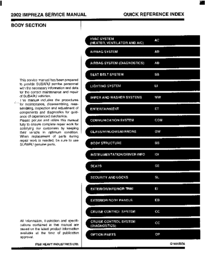
    2002 IMPREZA SERVICE MANUAL                         QUICK REFERENCE INDEX

    BODY SECTION


            This service manual has been prepared
            to provide SUBARU service personnel
            with the necessary information and data
            for the correct maintenance and repair
            of SUBARU vehicles.
            This manual includes the procedures
     c-   -
            for maintenance, disassembling, reas-
            sembling, inspection and adjustment of
            components and diagnostics for guid-
            ance of experienced mechanics.
            Please peruse and utilize this manual
            fully to ensure complete repair work for
            satisfying our customers by keeping
            their vehicle in optimum condition.
            When replacement of parts during
             repair work is needed, be sure to use
             SUBARU genuine parts.


           All information, illustration and specifi-
           cations contained in this manual are
           based on the latest product information
           available at the time of publication
           approval.

                      FUJI HEAVY INDUSTRIES LTD.                        Gl830BE6
HVAC SYSTEM
(HEATER. VENTILATOR AND A/C)

                                                                                                      ACa
                                                                                                                           Page
         1.    General Description .................................................................................... 2
         2.    Refrigerant Pressure with Manifold Gauge Set ......................................... 15
         3.    Refrigerant Recovery Procedure............................................................... 16
         4.    Refrigerant Charging Procedure ............................................................... 17
         5.    Refrigerant Leak Check ............................................................................ 20
         6.    Compressor Oil .........................................................................................      21
         7.    Blower Motor Unit Assembly ..................................................................... 22
         8.    Blower Resistor ......................................................................................... 23
         9.    Heater Core............................................................................................... 24
.
.       10.    Control Unit ............................................................................................... 25
        11.    Compressor............................................................................................... 26
        12.    Condenser................................................................................................. 27
        13.    Heater and Cooling Unit ............................................................................ 28
        14.    Evaporator................................................................................................. 29
        15.    Hose and Tube .......................................................................................... 30
        16.    Relay and Fuse ......................................................................................... 31
        17.    Pressure Switch (Dual Switch) .................................................................. 32
        18.    Air Vent Grille ............................................................................................ 33
        19.    Heater Duct ............................................................................................... 34
        20.    Heater Vent Duct....................................................................................... 35
        21 .   General Diagnostics.................................................................................. 36
                                     GENERAL DESCRIPTION
HVAC SYSTEM (HEATER, VENTILATOR AND N C )

1. General Description
A: SPECIFICATIONS
1. HEATER SYSTEM

                     Item                       SDecifications                             Condition
                                                                         Mode selector switch: HEAT
                                                                         Temperature control switch: FULL HOT
                                      5.0 kW (4,300 kcal/h, 17,062 BTU/ Temperature difference between hot water
Heating capacity
                                      h) or more                        and inlet air: 65
◦ Jabse Service Manual Search 2024 ◦ Jabse Pravopis ◦ onTap.bg ◦ Other service manual resources online : Fixya ◦ eServiceinfo