Service Manuals, User Guides, Schematic Diagrams or docs for : . Car Manuals Subaru Legacy 1995-1999 Approved Subaru Legacy 1995 1995 Service Manual 1995 LEGACY SUPPLEMENT Wheels And Axles Service Procedure-Front And Rear Drive Shafts_MSA5T9506A29533
<< Back | HomeMost service manuals and schematics are PDF files, so You will need Adobre Acrobat Reader to view : Acrobat Download Some of the files are DjVu format. Readers and resources available here : DjVu Resources
For the compressed files, most common are zip and rar. Please, extract files with Your favorite compression software ( WinZip, WinRAR ... ) before viewing. If a document has multiple parts, You should download all, before extracting.
Good luck. Repair on Your own risk. Make sure You know what You are doing.
Image preview - the first page of the document
>> Download Service Procedure-Front And Rear Drive Shafts_MSA5T9506A29533 documenatation <<
Text preview - extract from the document
4-2 [W4B2] SERVICE PROCEDURE
4. Front and Rear Drive Shafts
4. Front and Rear Drive Shafts
B : DISASSEMBLY
2. FWD MODEL
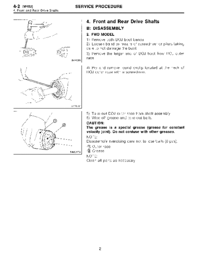
1) Remove both DOJ boot bands.
2) Loosen band by means of screwdriver or pliers taking
care to not damage the boot .
3) Remove the larger end of DOJ boot from DOJ outer
race.
4) Pry and remove round circlip located at the neck of
DOJ outer race with a screwdriver.
5) Take out DOJ outer race from shaft assembly .
6) Wipe off grease and take out balls .
CAUTION:
The grease is a special grease (grease for constant
velocity joint) . Do not confuse with other greases.
NOTE :
Disassemble exercising care not to lose balls (6 pcs) .
10 Outer race
~2 Grease
NOTE :
Clean all parts as necessary.
2
SERVICE PROCEDURE [waB2] 4-2
4. Front and Rear Drive Shafts
7) To remove the cage from the inner race, turn the cage
by a half pitch to the track groove of the inner race and
shift the cage .
8) Remove snap ring, which holds the inner race to shaft,
by using pliers .
9) Take out DOJ inner race.
10) Take off DOJ cage from shaft and remove DOJ boot .
CAUTION:
Be sure to wrap shaft splines with vinyl tape to protect
the boot from scratches .
11) Place drive shaft in a vise between wooden blocks .
CAUTION :
Do not place drive shaft directly in the vise; use wooden
block .
12) Raise boot band claws by means of screwdriver and
hammer.
o
r
\,1,
Boot band claws
B4M0689A
13) Cut and remove the boot.
CAUTION :
The boot must be replaced with a new one whenever it
is removed .
3
4-2 [W4D2] SERVICE PROCEDURE
4. Front and Rear Driv e Shafts
14) Thus, disassembly of axle is completed, but UFJ can-
not be disassembled .
D: ASSEMBLY
2. FWD MODEL
Use specified grease.
UFJ side:
UFJ (Front) - NTG2218 (Part No. 28093AA020)
DOJ side:
AT model (Front) - VU-3A702 (Yellow) (Part No.
23223GA050)
MT model (Front) - Molylex No. 2 (Part No.
723223010) or Sunlight TB2-A
1) Place UFJ boot and small boot band on UFJ side of
shaft.
CAUTION:
Be sure to wrap shaft splines with vinyl tape to prevent
boot from scratches.
2) Place drive shaft in a vise.
CAUTION:
Do not place drive shaft directly in the vise; use wooden
blocks .
3) Apply a coat of specified grease [60 to 70 g (2.12 to
2.47 oz)] to UFJ.
4) Apply an even coat of specified grease [20 to 30 g (0 .71
to 1 .06 oz)] to the entire inner surface of boot. Also apply
grease to shaft .
NOTE :
The inside of the larger end of UFJ boot and the boot
groove shall be cleaned so as to be free from grease and
other substances .
5) Install boot projecting portion to UFJ groove.
T U FJ
02 Large boot band
~3 Boot
6) Set large boot band in place.
4
SERVICE PROCEDURE [W4o21 4-2
4 . Front and Rear Drive Shafts
1 2 7) Align the boot end of the smaller diameter with the 3rd
groove in the drive shaft as shown in the figure .
10 Boot
T Small boot band
~3 Shaft
B4MO692A
8) Tighten boot bands using ST, torque wrench and
socket flex handle .
ST 28099AC000 BOOT BAND PLIER
ST I
J) Large boot band
(g) Boot
03 Torque wrench
Socket flex handle
~5 U FJ
B4MO693A
Tightening torque:
Large boot band
152 Mm (16.0 kg-m, 116 ft-Ib) or more
Small boot band
133 N~m (13.6 kg-m, 98 ft-Ib) or more
9) Place DOJ boot at the center of shaft.
Cage
10) Insert DOJ cage onto shaft .
NOTE:
IJIIIII Insert the cage with the cut-out portion facing the shaft
end, since the cage is directional .
- -I II i1 -
Cut-out portion
G4M0284
11) install DOJ inner race on shaft and fit snap ring with
pliers .
NOTE :
Confirm that the snap ring is completely fitted in the shaft
groove.
◦ Jabse Service Manual Search 2026 ◦ Jabse Pravopis ◦ onTap.bg ◦ Other service manual resources online : Fixya ◦ eServiceinfo