Service Manuals, User Guides, Schematic Diagrams or docs for : . Car Manuals Subaru Legacy 1995-1999 Approved Subaru Legacy 1995 1995 Service Manual ENGINE SECTION FUEL SYSTEM MSA5TCD95L5521
<< Back | HomeMost service manuals and schematics are PDF files, so You will need Adobre Acrobat Reader to view : Acrobat Download Some of the files are DjVu format. Readers and resources available here : DjVu Resources
For the compressed files, most common are zip and rar. Please, extract files with Your favorite compression software ( WinZip, WinRAR ... ) before viewing. If a document has multiple parts, You should download all, before extracting.
Good luck. Repair on Your own risk. Make sure You know what You are doing.
Image preview - the first page of the document
>> Download MSA5TCD95L5521 documenatation <<
Text preview - extract from the document
  SERVICE PROCEDURE                                             2-8
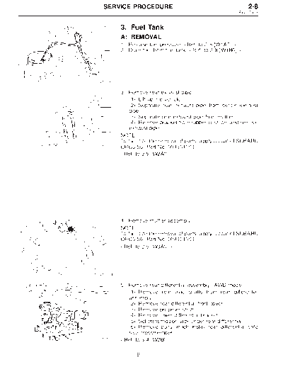
                                                         3. Fuel Tank


          3. Fuel Tank
          A: REMOVAL
          1) Release fuel pressure.
          2) Drain fuel from fuel tank.


G2M0345


          3) Remove rear exhaust pipe.
              (1) Lift-up the vehicle.
              (2) Separate rear exhaust pipe from center exhaust
              pipe.
              (3) Separate rear exhaust pipe from muffler.
              (4) Remove bracket from rubber cushion, and remove
              exhaust pipe.
          NOTE:
          To facilitate the removal of parts, apply a coat of SUBARU
G2M0382
          CRC5-56 (Part No. 004301003)


          4) Remove muffler assembly.
          NOTE:
          To facilitate the removal of parts, apply a coat of SUBARU
          CRC5-56 (Part No. 004301003)


G2M0384


          5) Remove rear differential assembly. (AWD model)
             (1) Remove rear axle shafts from rear differential
             assembly.
             (2) Remove rear differential front cover.
             (3) Remove propeller shaft.
             (4) Remove lower differential bracket.
             (5) Set transmission jack under rear differential.
             (6) Remove bolts which install rear differential onto
             rear crossmember.
G3M0059


                9
2-8               SERVICE PROCEDURE
3. Fuel Tank


                          6) Remove rear crossmember. (AWD model)


               G4M0545


                          7) Loosen clamp, and disconnect fuel filler hose from pipe.
                          8) Loosen clamp, and disconnect air vent hose from air
                          vent pipe.
                          k Fuel filler hose
                           1
                          k Air vent hose
                           2


               G2M0353


                          9) Loosen clip and clamps, and disconnect fuel delivery
                          hose k , return hose k and evaporation hose k .
                               1               2                      3


               B2M0310A


                          10) While holding fuel tank, remove bolts from bands and
                          dismount fuel tank.
                          WARNING:
                          A helper is required to perform step 10).


               G2M0356


                          B: INSTALLATION
                          Installation is in the reverse order of removal. Do the fol-
                          lowing:
                          1) When installing fuel tank, have a helper hold fuel tank
                          while installing bands.
                          2) Before tightening band mounting bolts, connect fuel
                          system hoses.


                                10
  SERVICE PROCEDURE                                             2-8
                                                         3. Fuel Tank


          3) Install hose and hold down clips at positions indicated
          in Figure.
          Tightening torque:
               1.0 +0.5 Nm (0.1 +0.05 kg-m, 0.7 +0.4 ft-lb)
                   -0           -0              -0
          Type A: When fitting length is specified.
          Type B: When fitting length is not specified.
          k Fitting
           1
          k Clamp
           2
          k Hose
           3
G2M0357
             : 1.0 -- 4.0 mm (0.039 -- 0.157 in)
          L: 20 -- 25 mm (0.79 -- 0.98 in)


          k Hose
           1
          k Clip
           2
          k Pipe
           3
          Fuel return hose:
             L = 20 -- 25 mm (0.79 -- 0.98 in)
          Evaporation hose:
             L = 15 -- 20 mm (0.59 -- 0.79 in)

G2M0358


          4) Tighten band mounting bolts.
          Tightening torque:
             33
◦ Jabse Service Manual Search 2026 ◦ Jabse Pravopis ◦ onTap.bg ◦ Other service manual resources online : Fixya ◦ eServiceinfo