Service Manuals, User Guides, Schematic Diagrams or docs for : . Car Manuals Subaru Legacy 1995-1999 Approved Subaru Legacy 1995 1995 Service Manual ELECTRICAL SECTION BODY ELECTRICAL SYSTEM MSA5TCD95L5848
<< Back | HomeMost service manuals and schematics are PDF files, so You will need Adobre Acrobat Reader to view : Acrobat Download Some of the files are DjVu format. Readers and resources available here : DjVu Resources
For the compressed files, most common are zip and rar. Please, extract files with Your favorite compression software ( WinZip, WinRAR ... ) before viewing. If a document has multiple parts, You should download all, before extracting.
Good luck. Repair on Your own risk. Make sure You know what You are doing.
Image preview - the first page of the document
>> Download MSA5TCD95L5848 documenatation <<
Text preview - extract from the document
  SERVICE PROCEDURE                                                             6-2
                     11. Rear Wiper and Washer - 12. Rear Window Defogger


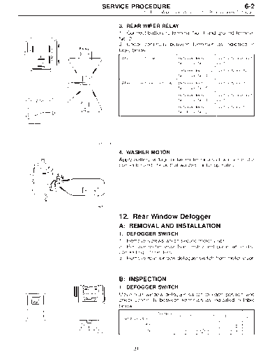
          3. REAR WIPER RELAY
          1) Connect battery to terminal No. 1 and ground terminal
          No. 2.
          2) Check continuity between terminals as indicated in
          table below:
          When current flows.           Between terminals       Continuity does not
                                        No. 3 and No. 5         exist.
                                        Between terminals       Continuity exists.
                                        No. 3 and No. 4
          When current does not flow.   Between terminals       Continuity exists.
                                        No. 3 and No. 5
                                        Between terminals       Continuity does not
                                        No. 3 and No. 4         exist.
                                        Between terminals       Continuity exists.
                                        No. 1 and No. 2


G6M0134

          4. WASHER MOTOR
          Apply battery voltage between terminals of washer motor
          connector and check that washer motor operates.


B6M0111


          12. Rear Window Defogger
          A: REMOVAL AND INSTALLATION
          1. DEFOGGER SWITCH
          1) Remove screws which secure meter visor.
          2) Remove meter visor from instrument panel while dis-
          connecting connectors.
          3) Remove rear window defogger switch from meter visor.


          B: INSPECTION
          1. DEFOGGER SWITCH
          Move rear window defogger switch to each position and
          check continuity between terminals as indicated in table
          below:
                            Terminal
                                        3    5              1       4            2
          Switch position
                      OFF                                           k            k
                       ON               k    k              k       k            k
B6M0119


                31
6-2                          SERVICE PROCEDURE
12. Rear Window Defogger


                                     2. DEFOGGER RELAY
                                     Check continuity between terminals as indicated in table
                                     below, when connecting the battery to terminal No. 1 and
                                     No. 3.
                                                                   Between terminals
                                     When current flows.                               Continuity exists.
                                                                   No. 2 and No. 4
                                                                   Between terminals   Continuity does not
                                                                   No. 2 and No. 4     exist.
                                     When current does not flow.
                                                                   Between terminals
                                                                                       Continuity exists.
                                                                   No. 1 and No. 3


                           G6M0112

                                     3. HEAT WIRES
                                     1) Start the engine so that battery is being charged.
                                     2) Turn defogger switch to ON.
                                     3) Check each heat wire at its center position for discon-
                                     tinuity by setting direct current voltmeter.
                                     Normal indication is about 6 volts.


                           G6M0135


                                     NOTE:
                                     When measuring voltage, wind a piece of tin foil around the
                                     tip of the tester probe and press the foil against the wire
                                     with your finger.


                           G6M0136


                                            32
  SERVICE PROCEDURE                                                 6-2
                         12. Rear Window Defogger - 13. Combination Meter


          4) When tester indicates 12 volts when its probe reaches
          point "A", a broken circuit occurs between point "A" and the
          negative terminal. Slowly move tester probe toward the
          negative terminal while contacting it on heat wire to locate
          point where tester indication changes abruptly (0 volts).
          This is the point where a broken circuit occurs.
          When tester indicates 0 volts when its probe reaches point
          "A", a broken circuit occurs between point "A" and the posi-
          tive terminal. Locate a point where tester indication
          changes abruptly (12 volts) while slowly moving tester
          probe toward the positive terminal.


G6M0137


          C: REPAIR
          1) Clean broken wire and its surrounding area.
          2) Cut off slit on (used) thin film by 0.5 mm (0.020 in) width
          and 10 mm (0.39 in) length.
          3) Place the slit on glass along the broken wire, and
          deposit conductive silver composition (DUPONT No. 4817)
          on the broken portion.
          4) Dry out the deposited portion.
          5) Inspect the repaired wire for continuity.
G6M0138


          13. Combination Meter
          A: REMOVAL AND INSTALLATION
          1.   COMBINATION METER
          1)   Move steering wheel fully down.
          2)   Remove screws which secure meter visor.
          3)   Remove visor from instrument panel.
          4)   Disconnect connectors from meter visor.

B6M0120


          5) Remove screws which secure combination meter, and
          pull combination meter out.
          6) Disconnect connectors from back of combination meter.
          CAUTION:
          When installing combination meter, be sure to connect
          connectors to backside of combination meter.


B6M0121


                 33
◦ Jabse Service Manual Search 2026 ◦ Jabse Pravopis ◦ onTap.bg ◦ Other service manual resources online : Fixya ◦ eServiceinfo