Service Manuals, User Guides, Schematic Diagrams or docs for : . Car Manuals Subaru Legacy 1995-1999 Approved Subaru Legacy 1995 1995 Service Manual ELECTRICAL SECTION BODY ELECTRICAL SYSTEM MSA5TCD95L5858
<< Back | HomeMost service manuals and schematics are PDF files, so You will need Adobre Acrobat Reader to view : Acrobat Download Some of the files are DjVu format. Readers and resources available here : DjVu Resources
For the compressed files, most common are zip and rar. Please, extract files with Your favorite compression software ( WinZip, WinRAR ... ) before viewing. If a document has multiple parts, You should download all, before extracting.
Good luck. Repair on Your own risk. Make sure You know what You are doing.
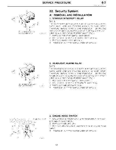
Image preview - the first page of the document
>> Download MSA5TCD95L5858 documenatation <<
Text preview - extract from the document
SERVICE PROCEDURE 6-2
22. Security System
22. Security System
A: REMOVAL AND INSTALLATION
1. STARTER INTERRUPT RELAY
NOTE:
The starter interrupt relay and headlight alarm relay use the
same parts and are mounted parallel to each other.
Therefore, before removal and installation, identify the
starter interrupt relay by the color of its wiring connection.
B6M0361A
1) Remove instrument panel lower cover.
2) Disconnect connector of starter interrupt relay.
3) Remove starter interrupt relay.
4) Installation is in the reverse order of removal.
2. HEADLIGHT ALARM RELAY
NOTE:
The headlight alarm relay and starter interrupt relay use the
same parts and are mounted parallel to each other.
Therefore, before removal and installation, identify the
headlight alarm relay by the color of its wiring connection.
1) Remove instrument panel lower cover.
2) Disconnect connector of headlight alarm relay.
B6M0361A 3) Remove headlight alarm relay.
4) Installation is in the reverse order of removal.
3. ENGINE HOOD SWITCH
1) Disconnect connector of engine hood switch from bot-
tom side of switch body.
2) Remove headlight (LH).
3) Remove attaching bolt, and then remove engine hood
switch.
4) Installation is in the reverse order of removal.
B6M0363A
51
6-2 SERVICE PROCEDURE
22. Security System
4. KEY CYLINDER LOCK/UNLOCK SWITCH AND
TAMPER SWITCH
NOTE:
The key cylinder lock switch, unlock switch and tamper
switch are united in the switch body.
Door Switch
1) Remove door trim panel and sealing cover.
2) Disconnect connector of door key cylinder switch from
B6M0364A
door cord.
3) Remove door outer handle.
CAUTION:
Be careful not to damage the door surface.
4) Remove clip, and then remove door key cylinder switch
from door outer handle.
5) Installation is in the reverse order of removal.
Trunk Lid Switch (SEDAN)
1) Disconnect connector of trunk lid key cylinder switch.
2) Disconnect rod from key cylinder.
3) Remove trunk lid key cylinder switch by pushing it.
4) Installation is in the reverse order of removal.
Rear Gate Switch (WAGON)
1) Disconnect connector of rear gate key cylinder switch.
2) Disconnect rod from key cylinder.
3) Remove attaching bolts, and then remove rear gate key
cylinder switch.
4) Installation is in the reverse order of removal.
B6M0368A
5. DOOR LOCK/UNLOCK SWITCH
NOTE:
The door lock/unlock switch is united with the power door
lock actuator.
Driver and Passenger Door
1) Remove door trim panel and sealing cover.
2) Disconnect connector of door lock actuator assembly
from door code.
52
SERVICE PROCEDURE 6-2
22. Security System
3) Remove door lock actuator assembly.
4) Installation is in the reverse order of removal.
Rear Gate (WAGON)
1) Remove rear gate trim panel.
2) Disconnect rod from rear gate latch assembly.
3) Disconnect rear gate switch connector and power door
lock actuator connector.
4) Remove bolts which secure power door lock actuator.
5) Remove bolts which secure latch.
6) Remove latch and actuator assembly.
7) Installation is in the reverse order of removal.
6. DOOR SWITCH
1) Remove rubber boot of door switch.
2) Remove screw which secures door switch to body.
3) Remove door switch while disconnecting connector.
B6M0070A
7. TRUNK LID SWITCH (SEDAN)
NOTE:
The trunk lid switch is united with the trunk lid lock.
1) Remove trunk rear trim.
2) Disconnect connector of trunk switch (combined with
trunk room light switch).
3) Put matching mark on the trunk lid lock and vehicle
body before removal.
4) Remove bolts, then remove trunk lid lock from vehicle
B6M0371A body.
5) Installation is in the reverse order of removal.
NOTE:
Ensure that matching mark is aligned between trunk lid
lock and vehicle body.
53
6-2 SERVICE PROCEDURE
22. Security System
8. REAR GATE SWITCH (WAGON)
NOTE:
The rear gate switch is united with the rear gate latch
assembly.
1) Remove rear gate trim panel.
2) Disconnect rod from rear gate latch assembly.
3) Disconnect rear gate switch (combined with luggage
room light switch) connector and power door lock actuator
connector.
B6M0372A 4) Remove bolts which secure power door lock actuator.
5) Remove bolts which secure latch.
6) Remove latch and actuator assembly.
7) Installation is in the reverse order of removal.
9. SECURITY INDICATOR LIGHT
1) Remove screws which secure meter visor.
2) Remove meter visor from instrument panel while dis-
connecting connectors.
3) Remove security indicator light from meter visor.
4) Installation is in the reverse order of removal.
B6M0373A
10. SECURITY CONTROL MODULE
1) Follow the same preparatory procedures when remov-
ing door lock timer.
2) Remove nut which secures security control module,
and remove security control module from bracket while
pulling right side lower end of instrument panel.
CAUTION:
Be careful not to damage instrument panel while pull-
ing its right side lower end.
B6M0682A
3) Disconnect connector from security control module.
4) Installation is in the reverse order of removal.
54
SERVICE PROCEDURE 6-2
22. Security System
B: INSPECTION
1. STARTER INTERRUPT RELAY
1) Disconnect connector of starter interrupt relay.
2) Connect battery to terminal No.1 and ground terminal
No. 2.
3) Check continuity between terminals as indicated in
table below:
When current flows. Between terminals Continuity does not
No. 3 and No. 5 exist.
When current does not flow. Between terminals Continuity exists.
No. 3 and No. 5
Between terminals Continuity exists.
No. 1 and No. 2
B6M0375A
2. HEADLIGHT ALARM RELAY
1) Disconnect connector of headlight alarm relay.
2) Connect battery to terminal No. 1 and ground terminal
No. 2.
3) Check continuity between terminals as indicated in
table below:
When current flows. Between terminals Continuity does not
No. 3 and No. 5 exist.
Between terminals Continuity exists.
No. 3 and No. 4
When current does not flow. Between terminals Continuity exists.
No. 3 and No. 5
Between terminals Continuity does not
No. 3 and No. 4 exist.
Between terminals Continuity exists.
No. 1 and No. 2
G6M0134
3. ENGINE HOOD SWITCH
1) Disconnect connector of engine hood switch.
2) Check continuity between terminals when push rod is
pushed in 1.5 mm (0.059 in) of its stroke.
Terminal
1 2
Switch position
When push rod is
pushed in.
When push rod is
k k
B6M0376 released.
55
6-2 SERVICE PROCEDURE
22. Security System
4. KEY CYLINDER LOCK/UNLOCK SWITCH AND
TAMPER SWITCH
Door Switch
1) Disconnect connector of door key cylinder switch.
2) Move switch by turning the key cylinder with ignition key
and/or remove switch from key cylinder to check continuity
between terminals as indicated in table below:
Terminal
1 2 3 4
Switch position
B6M0377
Normal
LOCK k k
UNLOCK k k
Switch is removed from
k k
key cylinder.
Trunk Lid Switch (SEDAN)
1) Disconnect connector of trunk lid key cylinder switch.
2) Move switch by turning the key cylinder with ignition key
and/or remove switch from key cylinder to check continuity
between terminals as indicated in table below:
Terminal
1 2 3
Switch position
Normal
B6M0378A UNLOCK k k
Switch is removed from
k k
key cylinder.
56
SERVICE PROCEDURE 6-2
22. Security System
Rear Gate Switch (WAGON)
1) Disconnect connector of rear gate key cylinder switch.
2) Move switch by turning the key cylinder with ignition key
and check continuity between terminals as indicated in
table below:
Terminal
1 2 4
Switch position
Normal
B6M0379 LOCK k k
UNLOCK k k
5. DOOR LOCK/UNLOCK SWITCH
NOTE:
The door lock/unlock switch is united with the power door
lock actuator.
1) Disconnect connector of door lock/unlock switch.
2) Set switch to each position and check continuity
between terminals as indicated in table below:
Driver's Door
Terminal
B6M0133A 1 2
Switch position
UNLOCK k k
LOCK
Passenger's Door
Terminal
1 2 3 4
Switch position
UNLOCK k k
LOCK
Rear Gate (WAGON)
B6M0381A
Terminal
1 2 3 4
Switch position
UNLOCK k k
LOCK
57
6-2 SERVICE PROCEDURE
22. Security System
6. DOOR SWITCH
Refer to 6-2 [W8B1] as for inspection of door switch.
NOTE:
The door switch is combined with the door switch for room
light.
7. TRUNK LID SWITCH (SEDAN)
Refer to 6-2 [W8B2] as for inspection of trunk lid switch.
NOTE:
The trunk lid switch is combined with the trunk room light
switch.
8. REAR GATE SWITCH (WAGON)
Refer to 6-2 [W8B3] as for inspection of rear gate switch.
NOTE:
The rear gate switch is combined with the luggage room
light switch.
9. SECURITY INDICATOR LIGHT
1) Remove security indicator light.
2) Check continuity between terminals of security indicator
light.
3) If there is no continuity, the indicator light will be fail-
ured.
Terminals: No. 2 -- No. 4
B6M0382A
10. SECURITY CONTROL MODULE
Refer to 6-2 [K600]: "6. SECURITY SYSTEM" for inspec-
tion of security control module.
58
SERVICE PROCEDURE 6-2
22. Security System
C: FUNCTION TEST
1. SECURITY SYSTEM OPERATION
1) Fully open all the door windows.
2) Turn the ignition switch to OFF and remove ignition key
from ignition switch.
3) Get out of the vehicle and lock the driver's door using a
ignition key.
4) Check that the security indicator light illuminates.
5) When the security indicator light illuminates, wait for 30
seconds.
After 30 seconds, check that the light starts repeating 0.2
sec. ON and 2.4 sec. OFF sequence.
6) Unlock the driver's door using the inside lock knob and
open the door.
Ensure that:
(1) the horn sounds and headlights flash intermittently
at 0.2 sec. ON and 0.6 sec. OFF. intervals, and
(2) the engine will not start even if the ignition switch
is turned to START.
7) Unlock the driver's door one time using the ignition key.
Ensure the horn and headlights turn off.
8) Close and lock the driver's door without using a ignition
key. (Set the inside lock knob to LOCK and then close the
door while lifting the outer handle).
Check that the security indicator light illuminates continu-
ously.
9) Within 30 seconds after the above step 8), unlock the
rear LH door using the inside lock knob and open the door.
Check that the security indicator light flashes at 0.5 sec.
intervals.
10) Close the rear LH door and lock the door using the
inside lock knob.
Check that the security indicator light illuminates continu-
ously.
11) Perform the above steps 9) and 10) on the rear RH
door and front RH door.
12) Within 30 seconds after above step 11) has been
finished, pull the engine hood opener lever and open the
engine hood.
Check that the security indicator light flashes at 0.5 sec.
intervals.
13) Close the engine hood completely.
Check that the security indicator light illuminates continu-
ously.
59
6-2 SERVICE PROCEDURE
22. Security System
14) Within 30 seconds after the above step 13), pull the
trunk lid opener lever and open the trunk lid (SEDAN); or
unlock the rear gate by operating the driver's door inside
lock knob and open the rear gate (WAGON).
Check that the security indicator light flashes at 0.5 sec.
intervals.
15) Close the trunk lid completely (SEDAN); or close the
rear gate and lock by locking the driver's door using a igni-
tion key (WAGON).
Check that the security indicator light illuminates continu-
ously.
16) When the security indicator light illuminates
continuously, wait for 30 seconds.
After 30 seconds, check that the light starts repeating 0.2
sec. ON and 2.4 sec. OFF sequence.
17) Unlock the trunk lid (SEDAN) or rear gate (WAGON)
using a ignition key and open.
Check that the horn and headlights do not operate.
18) Close the trunk lid (SEDAN) or rear gate (WAGON).
19) Unlock and then lock the driver's door using a ignition
key and wait for 30 seconds.
After 30 seconds, check that the light starts repeating 0.2
sec. ON and 2.4 sec. OFF sequence.
20) Only WAGON model; unlock and then lock the rear
gate using a ignition key and wait for 30 seconds.
After 30 seconds, check that the light starts repeating 0.2
sec. ON and 2.4 sec. OFF sequence.
21) Unlock the front RH door using a ignition key and open
the door.
Check that the horn and headlights do not operate.
After finishing the above checks, ensure that security sys-
tem's function is correct.
60
◦ Jabse Service Manual Search 2026 ◦ Jabse Pravopis ◦ onTap.bg ◦ Other service manual resources online : Fixya ◦ eServiceinfo