Service Manuals, User Guides, Schematic Diagrams or docs for : . Car Manuals Subaru Legacy 1995-1999 Approved Subaru Legacy 1995 1995 Service Manual WIRING DIAGRAM SECTION WIRING DIAGRAM MSA5TCD95L5928
<< Back | HomeMost service manuals and schematics are PDF files, so You will need Adobre Acrobat Reader to view : Acrobat Download Some of the files are DjVu format. Readers and resources available here : DjVu Resources
For the compressed files, most common are zip and rar. Please, extract files with Your favorite compression software ( WinZip, WinRAR ... ) before viewing. If a document has multiple parts, You should download all, before extracting.
Good luck. Repair on Your own risk. Make sure You know what You are doing.
Image preview - the first page of the document
>> Download MSA5TCD95L5928 documenatation <<
Text preview - extract from the document
6-3 WIRING DIAGRAM
2. Basic Diagnostics Procedures
2. Basic Diagnostics Procedures
The most important purpose of diagnostics is to determine
which part is malfunctioning quickly, to save time and labor.
A: IDENTIFICATION OF TROUBLE SYMPTOM
Determine what the problem is based on the symptom.
B: PROBABLE CAUSE OF TROUBLE
Look at the wiring diagram and check the system's circuit.
Then check the switch, relay, fuse, ground, etc.
C: LOCATION AND REPAIR OF TROUBLE
1) Using the diagnostics narrow down the causes.
2) If necessary, use a voltmeter, ohmmeter, etc.
3) Before replacing certain component parts (switch, relay,
etc.), check the power supply, ground, for open wiring
harness, poor connectors, etc. If no problems are
encountered, check the component parts.
D: CONFIRMATION OF SYSTEM OPERATION
After repairing, ensure that the system operates properly.
E: INSPECTION
1. VOLTAGE MEASUREMENT
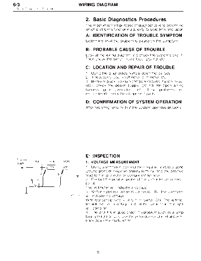
1) Using a voltmeter, connect the negative lead to a good
ground point or negative battery terminal and the positive
lead to the connector or component terminal.
2) Contact the positive probe of the voltmeter on connec-
tor (A).
The voltmeter will indicate a voltage.
3) Shift the positive probe to connector (B). The voltmeter
G6M0206
will indicate no voltage.
With test set-up held as it is, turn switch ON. The voltme-
ter will indicate a voltage and, at the same time, the light
will come on.
4) The circuit is in good order. If a problem such as a lamp
failing to light occurs, use the procedures outlined above to
track down the malfunction.
8
WIRING DIAGRAM 6-3
2. Basic Diagnostics Procedures
2. CIRCUIT CONTINUITY CHECKS
1) Disconnect the battery terminal or connector so there is
no voltage between the check points.
Contact the two leads of an ohmmeter to each of the check
points.
If the circuit has diodes, reverse the two leads and check
again.
2) Use an ohmmeter to check for diode continuity.
When contacting the negative lead to the diode positive
G6M0207 side and the positive lead to the negative side, there should
be continuity.
When contacting the two leads in reverse, there should be
no continuity.
3) Symbol "o--o" indicates that continuity exists between
two points or terminals. For example, when a switch posi-
tion is "3", continuity exists among terminals 1, 3 and 6, as
shown in table below.
Terminal
1 2 3 4 5 6
Switch Position
OFF
1 k k k
2 k k k
3 k k k
4 k k k
9
6-3 WIRING DIAGRAM
2. Basic Diagnostics Procedures
3. HOW TO DETERMINE AN OPEN CIRCUIT
1) Voltmeter method
An open circuit is determined by measuring the voltage
between respective connectors and ground using a
voltmeter, starting with the connector closest to the power
supply. The power supply must be turned ON so that cur-
rent flows in the circuit. If voltage is not present between a
particular connector and ground, the circuit between that
connector and the previous connector is open.
G6M0208
2) Ohmmeter method
Disconnect all connectors affected, and check continuity in
the wiring between adjacent connectors. When the ohm-
meter indicates "infinite", the wiring is open.
G6M0209
4. HOW TO DETERMINE A SHORT-CIRCUIT
1) Test lamp method
Connect a test lamp (rated at approximately 3 watts) in
place of the blown fuse and allow current to flow through
the circuit. Disconnect one connector at a time from the
circuit, starting with the one located farthest from the power
supply. If the test lamp goes out when a connector is
disconnected, the wiring between that connection and the
next connector (farther from the power supply) is shorted.
G6M0210
2) Ohmmeter method
Disconnect all affected connectors, and check continuity
between each connector and ground. When ohmmeter
indicates continuity between a particular connector and
ground, that connector is shorted.
G6M0211
10
WIRING DIAGRAM 6-3
3. Working Precautions
3. Working Precautions
1. PRECAUTIONS WHEN WORKING WITH THE
PARTS MOUNTED ON THE VEHICLE
1) When working under a vehicle which is jacked-up,
always be sure to use safety stands.
2) The parking brake must always be applied during work-
ing. Also, in automatic transmission vehicles, keep the
select lever set to the P (Parking) range.
3) Be sure the workshop is properly ventilated when run-
ning the engine. Further, be careful not to touch the belt or
fan while the engine is operating.
4) Be careful not to touch hot metal parts, especially the
radiator and exhaust system immediately after the engine
has been shut off.
2. PRECAUTIONS IN TROUBLE DIAGNOSIS AND
REPAIR OF ELECTRIC PARTS
1) The battery cable must be disconnected from the bat-
tery's (-) terminal, and the ignition switch must be set to the
OFF position, unless otherwise required by the diagnos-
tics.
2) Securely fasten the wiring harness with clamps and
slips so that the harness does not interfere with the body
end parts or edges and bolts or screws.
3) When installing parts, be careful not to catch them on
the wiring harness.
4) When disconnecting a connector, do not pull the wires,
but pull while holding the connector body.
G6M0212
11
6-3 WIRING DIAGRAM
3. Working Precautions
5) Some connectors are provided with a lock. One type of
such a connector is disconnected by pushing the lock, and
the other, by moving the lock up. In either type the lock
shape must be identified before attempting to disconnect
the connector.
To connect, insert the connector until it snaps and confirm
that it is tightly connected.
G6M0213
6) When checking continuity between connector terminals,
or measuring voltage across the terminal and ground,
always contact tester probe(s) on terminals from the wiring
connection side. If the probe is too thick to gain access to
the terminal, use "mini" test leads.
To check water-proof connectors (which are not accessible
from the wiring side), contact test probes on the terminal
side being careful not to bend or damage the terminals.
G6M0214
7) Sensors, relays, electrical unit, etc., are sensitive to
strong impacts.
Handle them with care so that they are not dropped or
mishandled.
12
WIRING DIAGRAM 6-3
4. How to Use Wiring Diagram
4. How to Use Wiring Diagram
B6M0213A
A: RELAY D: FUSE No. & RATING
A symbol used to indicate a relay. The "FUSE No. & RATING" corresponds that
used in the fuse box (main fuse box, and joint
B: CONNECTOR-1 box).
The sketch of the connector indicates the one-
pole types. E: CONNECTOR-2
1. Each connector is indicated by a symbol.
C: WIRING CONNECTION 2. Each terminal number is indicated in the cor-
Some wiring diagrams are indicated in foldouts responding wiring diagram in an abbreviated
for convenience. Wiring destinations are indi- form.
cated where necessary by corresponding sym- 3. For example, terminal number "C2" refers to
bols (as when two pages are needed for clear No. 2 terminal of connector (C:F41) shown in
indication). the connector sketch.
13
6-3 WIRING DIAGRAM
4. How to Use Wiring Diagram
F: CONNECTOR SKETCH J: SYMBOLS OF WIRE CONNECTION
1. Each connector sketch clearly identifies the AND CROSSING
shape and color of a connector as well as Symbol Refers to wires which are
terminal locations. Non-colored connectors connected and branched
are indicated in natural color. at the "dot" point.
2. When more than two types of connector Symbol Refers to wires which are
number are indicated in a connector sketch, crossed but not con-
it means that the same type connectors are nected.
used.
K: POWER SUPPLY ROUTING
G: GROUND A symbol is used to indicate the power supply in
each wiring diagram.
Each grounding point can be located easily by
"MB-5", "MB-6", etc., which are used as power
referring to the corresponding wiring harness. supply symbols throughout the text, correspond
with those shown in the POWER SUPPLY
H: DIODE ROUTING in the wiring diagram.
A symbol is used to indicate a diode. Accordingly, using the POWER SUPPLY ROUT-
ING and wiring diagrams permits service per-
I: WIRE TRACING ON EXTENDED sonnel to understand the entire electrical
WIRING DIAGRAMS arrangement of a system.
For a wiring diagram extending over at least two L: S.M.J.
pages, a symbol (consisting of the same charac-
A symbol is used to indicate the terminal
ters with arrows), as shown below, facilitates arrangement of the super multiple junction. The
wire tracing from one page to the next. S.M.J. is not shown in respective wiring dia-
A ) A, B ) B grams but is indicated on the next page.
SYMBOLS AND ABBREVIATIONS
A number of symbols and abbreviations are used
in each wiring diagram to easily identify parts or
circuits.
14
WIRING DIAGRAM 6-3
5. How to Use Super Multiple Junction (S.M.J.)
5. How to Use Super Multiple Junction
(S.M.J.)
The "S.M.J." indicated in wiring diagrams is shown in a
simplified form.
TERMINAL ARRANGEMENT
◦ Jabse Service Manual Search 2026 ◦ Jabse Pravopis ◦ onTap.bg ◦ Other service manual resources online : Fixya ◦ eServiceinfo