Service Manuals, User Guides, Schematic Diagrams or docs for : . Car Manuals Subaru Legacy 1995-1999 Approved Subaru Legacy 1995 1995 Service Manual TRANSMISSION AND DIFFERENTIAL SECTION MANUAL TRANSMISSION AND DIFFERENTIAL MSA5TCD95L5565
<< Back | HomeMost service manuals and schematics are PDF files, so You will need Adobre Acrobat Reader to view : Acrobat Download Some of the files are DjVu format. Readers and resources available here : DjVu Resources
For the compressed files, most common are zip and rar. Please, extract files with Your favorite compression software ( WinZip, WinRAR ... ) before viewing. If a document has multiple parts, You should download all, before extracting.
Good luck. Repair on Your own risk. Make sure You know what You are doing.
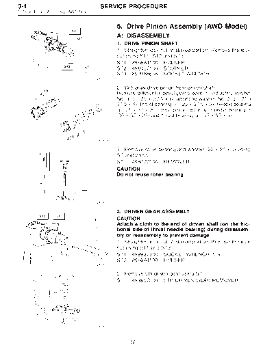
Image preview - the first page of the document
>> Download MSA5TCD95L5565 documenatation <<
Text preview - extract from the document
3-1                                      SERVICE PROCEDURE
5. Drive Pinion Assembly (AWD Model)


                                                 5. Drive Pinion Assembly (AWD Model)
                                                 A: DISASSEMBLY
                                                 1. DRIVE PINION SHAFT
                                                 1) Straighten lock nut at staked portion. Remove the lock
                                                 nut using ST1, ST2 and ST3.
                                                 ST1 899884100 HOLDER
                                                 ST2 498427100 STOPPER
                                                 ST3 899988608 SOCKET WRENCH
                                       G3M0595


                                                 2) Withdraw drive pinion from driven shaft.
                                                 Remove differential bevel gear sleeve k , adjusting washer
                                                                                         1
                                                 No. 1 k (25 x 37.5 x t), adjusting washer No. 2 k (25 x
                                                        2                                            3
                                                 37.5 x 4), thrust bearing k (25 x 37.5 x 3), needle bearing
                                                                           4
                                                 k (25 x 30 x 20), drive pinion collar k , needle bearing k
                                                  5                                    6                   7
                                                 (30 x 37 x 23) and thrust bearing k (33 x 50 x 3).
                                                                                    8


                                       G3M0606

                                                 3) Remove roller bearing and washer (33 x 50 x 5) using
                                                 ST and press.
                                                 ST   498077000 REMOVER
                                                 CAUTION:
                                                 Do not reuse roller bearing.


                                       G3M0607


                                                 2. DRIVEN GEAR ASSEMBLY
                                                 CAUTION:
                                                 Attach a cloth to the end of driven shaft (on the fric-
                                                 tional side of thrust needle bearing) during disassem-
                                                 bly or reassembly to prevent damage.
                                                 1) Straighten lock nut at staked portion. Remove the lock
                                                 nut using ST1 and ST2.
                                                 ST1 499987300 SOCKET WRENCH (50)
                                                 ST2 899884100 HOLDER
                                       G3M0608

                                                 2) Remove 5th driven gear using ST.
                                                 ST   499857000 5TH DRIVEN GEAR REMOVER


                                       G3M0609


                                                       50
   SERVICE PROCEDURE                                                       3-1
                                           5. Drive Pinion Assembly (AWD Model)


           3) Remove woodruff key.
           4) Remove roller bearing (42 x 74 x 40), 3rd and 4th driven
           gear using ST1 and ST2.
           ST1 499757002 SNAP RING PRESS
           ST2 899714110 REMOVER


G3M0610


           5) Remove the key.
           6) Remove 2nd driven gear assembly.
           7) Remove 1st driven gear, 2nd gear bushing, gear and
           hub using ST1 and ST2.
           Replace gear and hub if necessary. Do not attempt to dis-
           assemble if at all possible because they must engage at a
           specified point. If they have to be disassembled, mark the
           engaging point beforehand.
           ST1 499757002 SNAP RING PRESS
 G3M0611   ST2 899714110 REMOVER

           8) Remove sub gears for 1st and 2nd driven gear.


           B: ASSEMBLY
           1. GEAR AND HUB ASSEMBLY
           NOTE:
           Position open ends of springs 120
◦ Jabse Service Manual Search 2026 ◦ Jabse Pravopis ◦ onTap.bg ◦ Other service manual resources online : Fixya ◦ eServiceinfo