Service Manuals, User Guides, Schematic Diagrams or docs for : . Car Manuals Subaru Legacy 1995-1999 Approved Subaru Legacy 1995 1995 Service Manual TROUBLESHOOTING SECTION BRAKES [ABS-TCS] MSA5TCD95L5904
<< Back | HomeMost service manuals and schematics are PDF files, so You will need Adobre Acrobat Reader to view : Acrobat Download Some of the files are DjVu format. Readers and resources available here : DjVu Resources
For the compressed files, most common are zip and rar. Please, extract files with Your favorite compression software ( WinZip, WinRAR ... ) before viewing. If a document has multiple parts, You should download all, before extracting.
Good luck. Repair on Your own risk. Make sure You know what You are doing.
Image preview - the first page of the document
>> Download MSA5TCD95L5904 documenatation <<
Text preview - extract from the document
4-4b                                                     BRAKES
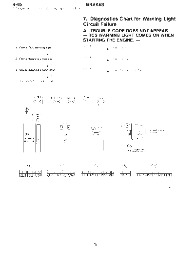
7. Diagnostics Chart for Warning Light Circuit Failure


                                                     7. Diagnostics Chart for Warning Light
                                                     Circuit Failure
                                                     A: TROUBLE CODE DOES NOT APPEAR.
                                                     -- TCS WARNING LIGHT COMES ON WHEN
                                                     STARTING THE ENGINE. --
                                                    Not OK
  1. Check TCS warning light.                                     Repair harness.

                           OK

  2. Check diagnosis terminal.                      Not OK        Repair harness.

                           OK

  3. Check diagnosis connector.                     Not OK        Repair harness/connector.

                           OK

  Replace ABS/TCS control module.


                                                                                              B4M0385


                                                             18
            BRAKES                                                    4-4b
                        7. Diagnostics Chart for Warning Light Circuit Failure


           1. CHECK TCS WARNING LIGHT.
           1) Turn ignition switch OFF.
           2) Disconnect all connectors from ABS/TCS control mod-
           ule.
           3) Turn ignition switch ON.
           4) Measure voltage between ABS/TCS control module
           connector and body.
           Connector & terminal / Specified voltage:
               (P6) No. 3 -- body / 10 -- 14 V
B4M0715A


           2. CHECK DIAGNOSIS TERMINAL.
           1) Turn ignition switch OFF.
           2) Measure resistance between diagnosis terminal and
           body.
           Connector/Specified resistance:
              B81 -- body / 0


B4M0387A

           3. CHECK DIAGNOSIS CONNECTOR.
           1) Turn ignition switch OFF.
           2) Disconnect all connectors from ABS/TCS control mod-
           ule.
           3) Measure resistance between diagnosis connector and
           body.
           Connector & terminal / Specified resistance:
               (B82) No. 4 -- body / 0

B4M0388A


                19
4-4b                                                     BRAKES
7. Diagnostics Chart for Warning Light Circuit Failure


                                                     B: ABS AND TCS WARNING LIGHT DO NOT
                                                     GO OFF.
                                                     -- TCS OFF AND TCS OPERATING
                                                     INDICATOR LIGHTS COME ON AND GO OFF
                                                     PROPERLY WHEN STARTING THE ENGINE,
                                                     WHILE ABS WARNING AND TCS WARNING
                                                     LIGHTS KEEP ON. --
  1. Check brake fluid level.                       Not OK        Add to brake fluid.

                            OK

  2. Check brake fluid level sensor.                Not OK        Replace master cylinder.

                            OK

  3. Check harness connector between ABS/TCS        Not OK        Replace harness connector.
     control module and alternator.

                            OK

  Replace ABS/TCS control module.


                                                                                               B4M0389


                                                             20
            BRAKES                                                     4-4b
                         7. Diagnostics Chart for Warning Light Circuit Failure


           1. CHECK BRAKE FLUID LEVEL.
           Check that brake fluid level is above the MIN indication on
           the reservoir tank.


           2. CHECK BRAKE FLUID LEVEL SENSOR.
           1) Turn ignition switch OFF.
           2) Disconnect connector from brake fluid level sensor.
           Connector & terminal / Specified resistance:
              (B16) No. 1 -- No. 2 / 0  (Leaving float where it
                                        is.)
              (B16) No. 1 -- No. 2 / 1 M (When pushing float
                                          down.)

B4M0716A

           3. CHECK HARNESS CONNECTOR BETWEEN ABS/
           TCS CONTROL MODULE AND ALTERNATOR.
           1) Turn ignition switch OFF.
           2) Connect connector from brake fluid level sensor.
           3) Disconnect all connectors from ABS/TCS control mod-
           ule.
           4) Measure voltage between ABS/TCS control module
           connector and body.
           Connector & terminal / Specified voltage:
B4M0717A       (P7) No. 20 -- body / 2 V or less
           5) Start the engine.
           6) Measure voltage between ABS/TCS control module
           connector and body.
           Connector & terminal / Specified voltage:
               (P7) No. 20 -- body / 10 -- 14 V


                 21
4-4b                                                     BRAKES
7. Diagnostics Chart for Warning Light Circuit Failure


                                                     C: TCS WARNING LIGHT AND TCS
                                                     INDICATOR OFF AND TCS OPERATING
                                                     INDICATOR LIGHTS COME ON AND GO OFF
                                                     PROPERLY, WHILE ABS WARNING LIGHT
                                                     DOES NOT GO OFF.
                                                     -- TCS WARNING LIGHT AND TCS OFF
                                                     INDICATOR AND TCS OPERATING
                                                     INDICATOR LIGHTS COME ON AND GO OFF
                                                     PROPERLY WHEN STARTING THE ENGINE,
                                                     WHILE ABS WARNING LIGHT DOES NOT GO
                                                     OFF. --
  1. Check harness connector between ABS/TCS                      Repair harness connector.
     control module and ABS warning light.


  Replace ABS/TCS control module.


                                                                                              B4M0392


                                                           22
            BRAKES                                                   4-4b
                       7. Diagnostics Chart for Warning Light Circuit Failure


           1. CHECK HARNESS CONNECTOR BETWEEN ABS/
           TCS CONTROL MODULE AND ABS WARNING LIGHT.
           1) Turn ignition switch OFF.
           2) Disconnect connector from ABS/TCS control module
           and TCS valve relay.
           3) Measure resistance between ABS/TCS control module
           connector and body.
           Connector & terminal / Specified resistance:
              (P6) No. 2 -- body / 1 M or more
B4M0393A


                23
4-4b                                                     BRAKES
7. Diagnostics Chart for Warning Light Circuit Failure


                                                     D: ABS WARNING LIGHT ONLY REMAINS
                                                     ILLUMINATED.
                                                     -- WHEN STARTING THE ENGINE, NEITHER
                                                     TCS WARNING, TCS OFF INDICATOR NOR
                                                     TCS OPERATING INDICATOR LIGHT COMES
                                                     ON EVEN ONCE, AND ABS WARNING LIGHT
                                                     AND MALFUNCTION INDICATOR LAMP
                                                     ILLUMINATE. --
  1. Check input voltage of ABS/TCS control mod-    Not OK        Repair harness/connector.
     ule.

                           OK

  Replace ABS/TCS control module.


                                                                                              B4M0394


                                                             24
            BRAKES                                                   4-4b
                       7. Diagnostics Chart for Warning Light Circuit Failure


           1. CHECK INPUT VOLTAGE OF ABS/TCS CONTROL
           MODULE.
           1) Turn ignition switch OFF.
           2) Disconnect connector from ABS/TCS control module.
           3) Turn ignition switch ON.
           4) Measure voltage between ABS/TCS control module
           connector and body.
           Connector & terminal / Specified voltage:
              (P5) No. 1 -- body / 10 -- 13 V
B4M0395A
           NOTE:
◦ Jabse Service Manual Search 2026 ◦ Jabse Pravopis ◦ onTap.bg ◦ Other service manual resources online : Fixya ◦ eServiceinfo