Service Manuals, User Guides, Schematic Diagrams or docs for : . Car Manuals Subaru Legacy 1995-1999 Approved Subaru Legacy 1995 1995 Service Manual TROUBLESHOOTING SECTION ON-BOARD DIAGNOSTICS II SYSTEM MSA5TCD95L5869
<< Back | HomeMost service manuals and schematics are PDF files, so You will need Adobre Acrobat Reader to view : Acrobat Download Some of the files are DjVu format. Readers and resources available here : DjVu Resources
For the compressed files, most common are zip and rar. Please, extract files with Your favorite compression software ( WinZip, WinRAR ... ) before viewing. If a document has multiple parts, You should download all, before extracting.
Good luck. Repair on Your own risk. Make sure You know what You are doing.
Image preview - the first page of the document
>> Download MSA5TCD95L5869 documenatation <<
Text preview - extract from the document
ON-BOARD DIAGNOSTICS II SYSTEM                                          2-7
                                                          3. Diagnosis System


              3. Diagnosis System
              A: MALFUNCTION INDICATOR LAMP (MIL)
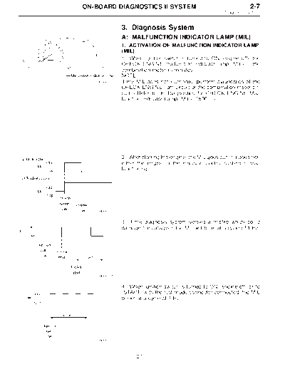
              1. ACTIVATION OF MALFUNCTION INDICATOR LAMP
              (MIL)
              1) When ignition switch is turned to ON (engine off), the
              CHECK ENGINE malfunction indicator lamp (MIL) in the
              combination meter illuminates.
              NOTE:
   OBD0008C   If the MIL does not illuminate, perform diagnostics of the
              CHECK ENGINE light circuit or the combination meter cir-
              cuit.


              2) After starting the engine, the MIL goes out. If it does not,
              either the engine or the emission control system is mal-
              functioning.


   OBD0053A


              3) If the diagnosis system senses a misfire which could
              damage the catalyzer, the MIL will blink at a cycle of 1 Hz.


   OBD0054A


              4) When ignition switch is turned to ON (engine off) or to
              "START" with the test mode connector connected, the MIL
              blinks at a cycle of 3 Hz.


   OBD0055A


                    27
2-7                                  ON-BOARD DIAGNOSTICS II SYSTEM
3. Diagnosis System


                                                              B: OBD-II GENERAL SCAN TOOL
                                                              1. HOW TO USE OBD-II GENERAL SCAN TOOL
                                                              1) Prepare a general scan tool (OBD-II general scan tool)
                                                              required by SAE J1978.
                                                              2) Open the cover and connect the OBD-II general scan
                                                              tool to the data link connector located in the lower portion
                                                              of the instrument panel (on the driver's side), to the lower
                                                              cover.
                                                              3) Using the OBD-II general scan tool, call up diagnostic
                                             OBD0006C
                                                              trouble code(s) and freeze frame data.
                                                              OBD-II general scan tool functions consist of:
                                                                  (1) MODE $01: Current powertrain diagnostic data
                                                                  (2) MODE $02: Powertrain freeze frame data
                                                                  (3) MODE $03: Emission-related powertrain diagnostic
                                                                  trouble codes
                                                                  (4) MODE $04: Clear/Reset emission-related diagnos-
                                                                  tic information
                                                                  (5) MODE $05: Oxygen sensor monitoring test results
                                                              Read out data according to repair procedures.
                                                              (For detailed operation procedures, refer to the OBD-II
                                                              General Scan Tool Operation Manual.)
                                                              NOTE:
                                                              For details concerning diagnostic trouble codes, refer to
                                                              the DIAGNOSTIC TROUBLE CODE (DTC) LIST [T11A0].


                                                              2. DATA LINK CONNECTOR (FOR OBD-II GENERAL
                                                              SCAN TOOL AND SUBARU SELECT MONITOR)
                                                              1) This connector is used both for OBD-II general scan
                                                              tools and Subaru Select Monitor.
                                                              2) Terminal No. 4 to No. 6 of data link connector is used
                                                              for Subaru Select Monitor signal.
                                                              CAUTION:
                                                              Do not connect scan tools other than OBD-II general
                                                              scan tools and Subaru Select Monitor, because the
                                                 H2M1280      circuit for Subaru Select Monitor may be damaged.
  Terminal No.                                     Contents                           Terminal No.             Contents
        1         Power supply                                                             9         Blank
        2         Blank                                                                   10         K line of ISO 9141 CARB
        3         Blank                                                                   11         Blank
        4         Subaru Select Monitor signal (ECM to Subaru Select monitor)*            12         Ground
        5         Subaru Select Monitor signal (Subaru Select monitor to ECM)*            13         Ground
        6         Subaru Select Monitor clock*                                            14         Blank
        7         Blank                                                                   15         Blank
        8         Blank                                                                   16         Blank
*: Circuit only for Subaru Select Monitor


                                                                    28
                             ON-BOARD DIAGNOSTICS II SYSTEM                                                        2-7
                                                                                                    3. Diagnosis System


                                                  3. READ DATA LIST
◦ Jabse Service Manual Search 2026 ◦ Jabse Pravopis ◦ onTap.bg ◦ Other service manual resources online : Fixya ◦ eServiceinfo