Service Manuals, User Guides, Schematic Diagrams or docs for : . Car Manuals Subaru Legacy 1995-1999 Approved Subaru Legacy 1996 1996 Service Manual MECHANICAL COMPONENTS SECTION BRAKES MSA5TCD96L6196
<< Back | HomeMost service manuals and schematics are PDF files, so You will need Adobre Acrobat Reader to view : Acrobat Download Some of the files are DjVu format. Readers and resources available here : DjVu Resources
For the compressed files, most common are zip and rar. Please, extract files with Your favorite compression software ( WinZip, WinRAR ... ) before viewing. If a document has multiple parts, You should download all, before extracting.
Good luck. Repair on Your own risk. Make sure You know what You are doing.
Image preview - the first page of the document
>> Download MSA5TCD96L6196 documenatation <<
Text preview - extract from the document
4-4                   SERVICE PROCEDURE
6. Brake Booster


                              6. Brake Booster
                              A: REMOVAL
                              1) Remove or disconnect the following parts at engine
                              compartment.
                                 (1) Disconnect connector for brake fluid level indicator.
                                 (2) Remove brake pipes from master cylinder.
                                 (3) Remove master cylinder installing nuts.
                                 (4) Disconnect vacuum hose from brake booster.
                              2) Remove the following parts from the pedal bracket.
                                 (1) Snap pin and clevis pin
                                 (2) Four brake booster installing nuts
                              3) Remove brake booster while shunning brake pipes.


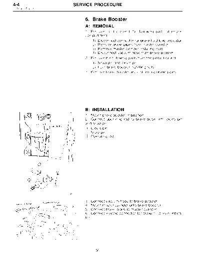
                              B: INSTALLATION
                              1) Mount brake booster in position.
                              2) Connect operating rod to brake pedal with clevis pin
                              and snap pin.
                              k Clevis pin
                               1
                              k Snap pin
                               2
                              k Operating rod
                               3


                   B4M0117A


                              3) Connect vacuum hose to brake booster.
                              4) Mount master cylinder onto brake booster.
                              5) Connect brake pipes to master cylinder.
                              6) Connect electric connector for brake fluid level indica-
                              tor.


                   G4M0420


                                    50
   SERVICE PROCEDURE                                                  4-4
                                                           6. Brake Booster


           7) Adjust operating rod of brake booster.
           Standard: L
                 145.3 mm (5.72 in)
           If it is not in specified value, adjust it by adjusting brake
           booster operating rod.
           8) Measure the clearance between threaded end of stop
           light switch and stopper.
           If it is not in specified value, adjust it by adjusting position
           of stop light switch.
B4M0616A
           k Stop light switch
            1
           k Stopper
            2
           k Brake pedal
            3
           CAUTION:
           Be careful not to rotate stop light switch.
           Stop light switch clearance: A
                 0.3 mm (0.012 in)
           9) Apply grease to operating rod connecting pin to prevent
           it from wearing.
           10) Bleed air from brake system.
B4M0617A
           Tightening torque (Air bleeder screw):
                 8
◦ Jabse Service Manual Search 2026 ◦ Jabse Pravopis ◦ onTap.bg ◦ Other service manual resources online : Fixya ◦ eServiceinfo