Service Manuals, User Guides, Schematic Diagrams or docs for : . Car Manuals Subaru Legacy 1995-1999 Approved Subaru Legacy 1996 1996 Service Manual MECHANICAL COMPONENTS SECTION HEATER AND VENTILATOR MSA5TCD96L6234
<< Back | HomeMost service manuals and schematics are PDF files, so You will need Adobre Acrobat Reader to view : Acrobat Download Some of the files are DjVu format. Readers and resources available here : DjVu Resources
For the compressed files, most common are zip and rar. Please, extract files with Your favorite compression software ( WinZip, WinRAR ... ) before viewing. If a document has multiple parts, You should download all, before extracting.
Good luck. Repair on Your own risk. Make sure You know what You are doing.
Image preview - the first page of the document
>> Download MSA5TCD96L6234 documenatation <<
Text preview - extract from the document
   SERVICE PROCEDURE                                                 4-6
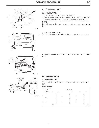
                                                            4. Control Unit


           4. Control Unit
           A: REMOVAL
           1) Disconnect GND cable from battery.
           2) Set temperature control lever to "FULL COLD" position.
           3) Remove temperature control cable from heater unit.
           NOTE:
           Do not attempt to move link of heater unit during installa-
           tion.
 B5M0027


           4) Remove cup holder.
           5) Remove center panel and then disconnect connector.


 B4M0370


           6) Remove control unit assembly and disconnect connec-
           tor.


 B4M0059


           B: INSPECTION
           1. FAN SWITCH
           Check continuity between terminals at each switch posi-
           tion.
           LHD model
            Switch                      Terminals
            position     1     2       3        4       5           6
               1        k      k                                    k
B4M0060A
               2        k              k                            k
               3        k                       k                   k
               4        k                               k           k
                        GND                                        IGN


                   13
4-6                  SERVICE PROCEDURE
4. Control Unit


                             RHD model
                              Switch                                       Terminals
                              position          1            2             3           4           5             6
                                     1                                     k          k                         k
                                     2                       k             k          k                         k
                                     3          k                          k          k                         k
                                     4                                     k          k            k            k
                                                                                     GND                        IGN

                             2. CONTROL UNIT
                             Check circuit continuity between each terminal, when push
                             control switch is turned ON.
                             LHD model
                                                    Mode selector switch              RECIRC switch
                             Terminal                                                                   A/C     Illumi.
                                No.                                 DEF/                               switch
                                         VENT   BI-LEV     HEAT                DEF   RECIRC FRESH
                                                                    HEAT

                                1

                                2
                  B4M0061A
                                3                                                                                    k

                                4

                                5                                              k

                                6                            k        k

                                7         k         k

                                8         k         k        k        k        k       k       k

                                9                                                              k

                                10                                                     k

                                11                                                                                   k

                                12        k         k        k        k        k

                                13

                                14                                    k        k

                                15                  k        k

                                16        k

                                17                                                                       k

                                18                                                                       k

                                19                                                                       k


                                         14
   SERVICE PROCEDURE                                                                    4-6
                                                                             4. Control Unit


           RHD model
                               Mode selector switch          RECIRC switch
           Terminal                                                            A/C     Illumi.
              No.                              DEF/                           switch
                      VENT   BI-LEV   HEAT            DEF   RECIRC FRESH
                                               HEAT

              1        k

              2                k

              3                         k

              4                                  k

              5                                       k

              6                                                       k

              7                                               k

              8                                                                 k

              9        k       k        k        k    k                         k

              10                                                                         k

              11

              12                                                                         k

              13       k       k        k        k    k       k       k         k

              14                                                                k

              15

              16                                                                k


           C: ADJUSTMENT
           1) Operate temperature control lever to "FULL COLD"
           position.
           2) Install control cable to lever k . While pushing outer
                                              1
           cable, secure control cable with clip k .
                                                 2


B4M0062A


           D: INSTALLATION
           Installation is in the reverse order of removal.
           NOTE:
           Before control unit installation, set temperature control
           lever to "FULL COLD" position.


                      15
◦ Jabse Service Manual Search 2026 ◦ Jabse Pravopis ◦ onTap.bg ◦ Other service manual resources online : Fixya ◦ eServiceinfo