Service Manuals, User Guides, Schematic Diagrams or docs for : . Car Manuals Subaru Legacy 1995-1999 Approved Subaru Legacy 1996 1996 Service Manual WIRING DIAGRAM SECTION WIRING DIAGRAM MSA5TCD96L6477
<< Back | HomeMost service manuals and schematics are PDF files, so You will need Adobre Acrobat Reader to view : Acrobat Download Some of the files are DjVu format. Readers and resources available here : DjVu Resources
For the compressed files, most common are zip and rar. Please, extract files with Your favorite compression software ( WinZip, WinRAR ... ) before viewing. If a document has multiple parts, You should download all, before extracting.
Good luck. Repair on Your own risk. Make sure You know what You are doing.
Image preview - the first page of the document
>> Download MSA5TCD96L6477 documenatation <<
Text preview - extract from the document
                                     WIRING DIAGRAM                                                6-3
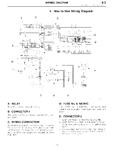
                                                                            4. How to Use Wiring Diagram


                                         4. How to Use Wiring Diagram


                                                                                               B6M0213A


A: RELAY                                              D: FUSE No. & RATING
A symbol used to indicate a relay.                    The "FUSE No. & RATING" corresponds that
                                                      used in the fuse box (main fuse box, and joint
B: CONNECTOR-1                                        box).
The sketch of the connector indicates the one-
pole types.                                           E: CONNECTOR-2
                                                      1. Each connector is indicated by a symbol.
C: WIRING CONNECTION                                  2. Each terminal number is indicated in the cor-
Some wiring diagrams are indicated in foldouts           responding wiring diagram in an abbreviated
for convenience. Wiring destinations are indi-           form.
cated where necessary by corresponding sym-           3. For example, terminal number "C2" refers to
bols (as when two pages are needed for clear             No. 2 terminal of connector (C:F41) shown in
indication).                                             the connector sketch.


                                                 13
6-3                                     WIRING DIAGRAM
4. How to Use Wiring Diagram


F: CONNECTOR SKETCH                                     J: SYMBOLS OF WIRE CONNECTION
1. Each connector sketch clearly identifies the         AND CROSSING
   shape and color of a connector as well as                 Symbol            Refers to wires which are
   terminal locations. Non-colored connectors                                  connected and branched
   are indicated in natural color.                                             at the "dot" point.
2. When more than two types of connector                     Symbol            Refers to wires which are
   number are indicated in a connector sketch,                                 crossed but not con-
   it means that the same type connectors are                                  nected.
   used.
                                                        K: POWER SUPPLY ROUTING
G: GROUND                                               A symbol is used to indicate the power supply in
                                                        each wiring diagram.
Each grounding point can be located easily by
                                                        "MB-5", "MB-6", etc., which are used as power
referring to the corresponding wiring harness.          supply symbols throughout the text, correspond
                                                        with those shown in the POWER SUPPLY
H: DIODE                                                ROUTING in the wiring diagram.
A symbol is used to indicate a diode.                   Accordingly, using the POWER SUPPLY ROUT-
                                                        ING and wiring diagrams permits service per-
I: WIRE TRACING ON EXTENDED                             sonnel to understand the entire electrical
WIRING DIAGRAMS                                         arrangement of a system.
For a wiring diagram extending over at least two        L: S.M.J.
pages, a symbol (consisting of the same charac-
                                                        A symbol is used to indicate the terminal
ters with arrows), as shown below, facilitates          arrangement of the super multiple junction. The
wire tracing from one page to the next.                 S.M.J. is not shown in respective wiring dia-
A ) A, B ) B                                            grams but is indicated on the next page.

                                                        SYMBOLS AND ABBREVIATIONS
                                                        A number of symbols and abbreviations are used
                                                        in each wiring diagram to easily identify parts or
                                                        circuits.


                                                   14
◦ Jabse Service Manual Search 2026 ◦ Jabse Pravopis ◦ onTap.bg ◦ Other service manual resources online : Fixya ◦ eServiceinfo