Service Manuals, User Guides, Schematic Diagrams or docs for : . Car Manuals Subaru Legacy 1995-1999 Approved Subaru Legacy 1996 1996 Service Manual TROUBLESHOOTING SECTION AUTOMATIC TRANSMISSION AND DIFFERENTIAL MSA5TCD96L6421

<< Back | Home

Most service manuals and schematics are PDF files, so You will need Adobre Acrobat Reader to view : Acrobat Download Some of the files are DjVu format. Readers and resources available here : DjVu Resources
For the compressed files, most common are zip and rar. Please, extract files with Your favorite compression software ( WinZip, WinRAR ... ) before viewing. If a document has multiple parts, You should download all, before extracting.
Good luck. Repair on Your own risk. Make sure You know what You are doing.


Image preview - the first page of the document
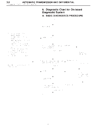
MSA5TCD96L6421


>> Download MSA5TCD96L6421 documenatation <<

Text preview - extract from the document
3-2                      AUTOMATIC TRANSMISSION AND DIFFERENTIAL
6. Diagnostic Chart for On-board Diagnostic System


                                                     6. Diagnostic Chart for On-board
                                                     Diagnostic System
                                                     A: BASIC DIAGNOSTICS PROCEDURE
                                                     TROUBLE OCCURS.


                                                     INTERVIEW


  1.   Oil level check 
  2.   Oil leak check 
  3.   Brake band adjustment 
  4.   Stall test 
  5.   Line pressure test                                       TEMP INDICATOR)
  6.   Transfer clutch pressure test
                                                 Not indicated.
  7.   Time lag test                                                                                                DIAGNOSTICS
  8.   Road test 


                                             OK                                             No trouble code
                                                     Inspection using Diagnostic Chart
                                                     with Select Monitor 3-2 [T800]                             Trouble code
  Inspection using General Diagnostic                                 Not OK
  Table 3-2 [T900].

                                                     Repair.
                                                                                                              Check in
                                                                                                              accordance with
                                                                                                              trouble code 3-2
                                                                                                              [T700].
                                                     CLEAR MEMORY


                                                                                         Trouble code
                                                     Confirmation test
                                                     (ON-BOARD DIAGNOSTICS)

                                                                      No trouble code


                                                     End


                                                               10
AUTOMATIC TRANSMISSION AND DIFFERENTIAL                                  3-2
                            6. Diagnostic Chart for On-board Diagnostic System


              B: ABNORMAL DISPLAY ON AT OIL TEMP
              INDICATOR
              When any on-board diagnostic item is malfunctioning, the
              display on the AT OIL TEMP indicator blinks immediately
              after the engine starts.
              The malfunctioning part or unit can be determined by a
              trouble code during on-board diagnostic operation. Prob-
              lems which occurred previously can also be identified
              through the memory function.
              If the AT OIL TEMP indicator does not show a problem
              (although a problem is occurring), the problem can be
              determined by checking the performance characteristics of
              each sensor using the select monitor.
              Indicator signal is as shown in the figure.
              WARNING:
              Warning can be noticed only when the engine is ini-
              tially started.


                                                                     B3M0410A


                    11
3-2                       AUTOMATIC TRANSMISSION AND DIFFERENTIAL
6. Diagnostic Chart for On-board Diagnostic System


                                                          C: ON-BOARD DIAGNOSTICS


* : Blinks every 0.125 (1/8) seconds (until ignition switch is turned OFF).
** : Blinks every 0.25 (1/4) seconds (until ignition switch is turned OFF).
*** : Plug in diagnosis terminal to diagnosis connector No. 5 located below instrument lower cover.


                                                                   12
               AUTOMATIC TRANSMISSION AND DIFFERENTIAL                                                    3-2
                                                             6. Diagnostic Chart for On-board Diagnostic System


                                          D: LIST OF TROUBLE CODE
                                          1. TROUBLE CODE
                                                                                    Abbr.
Trouble code            Item                     Content of diagnosis                              Page
                                                                               (Select monitor)
                                          Detects open or shorted drive
    11             Duty solenoid A                                                 PLDTY            15
                                          circuit, as well as valve seizure.
                                          Detects open or shorted drive
    12            Duty solenoid B                                                  LUDTY            19
                                          circuit, as well as valve seizure.
                                          Detects open or shorted drive
    13             Shift solenoid 3                                                 OVR             23
                                          circuit, as well as valve seizure.
                                          Detects open or shorted drive
    14             Shift solenoid 2                                                 SFT2            25
                                          circuit, as well as valve seizure.
                                          Detects open or shorted drive
    15             Shift solenoid 1                                                 SFT1            27
                                          circuit, as well as valve seizure.
                                          Detects open or shorted input
    21         ATF temperature sensor                                               ATFT            29
                                          signal circuit.
                                          Detects open or shorted input
    22           Mass air flow signal                                               AFM             32
                                          signal circuit.
                                          Detects open or shorted input
    23          Engine speed signal                                                EREV             34
                                          signal circuit.
                                          Detects open or shorted drive
    24            Duty solenoid C                                                  4WDTY            36
                                          circuit, as well as valve seizure.
                                          Detects open or shorted input
    25          Torque control signal                                              TQ.CT            38
                                          signal circuit.
                                          Detects open or shorted input
    31         Throttle position sensor                                             THV             40
                                          signal circuit.
                                          Detects open or shorted input
    32         Vehicle speed sensor 1                                               VSP1            43
                                          signal circuit.
                                          Detects open or shorted input
    33         Vehicle speed sensor 2                                               VSP2            47
                                          signal circuit.


                                                 13
3-2                   AUTOMATIC TRANSMISSION AND DIFFERENTIAL
6. Diagnostic Chart for On-board Diagnostic System


                                                     2. HOW TO READ TROUBLE CODE OF INDICATOR
                                                     LIGHT
                                                     The AT OIL TEMP indicator light flashes the code corre-
                                                     sponding to the faulty part.
                                                     The long segment (1.2 sec on) indicates a "ten", and the
                                                     short segment (0.2 sec on) signifies a "one".


                                                                                                       B3M0193A


                                                     E: CLEAR MEMORY
                                                 Current trouble codes shown on the display are cleared by
                                                 turning the ignition switch OFF after conducting on-board
                                                 diagnostic operation. Previous trouble codes, however,
                                                 cannot be cleared since they are stored in the TCM
                                                 memory which is operating on the back-up power supply.
                                                 These trouble codes can be cleared by removing the speci-
                                                 fied fuse (located under the right lower portion of the instru-
                                                 ment panel).
                                                 CLEAR MEMORY:
                                                      Removal of No. 14 fuse (for at least one minute)


◦ Jabse Service Manual Search 2026 ◦ Jabse PravopisonTap.bg ◦ Other service manual resources online : FixyaeServiceinfo