Service Manuals, User Guides, Schematic Diagrams or docs for : . Car Manuals Subaru Legacy 1995-1999 Approved Subaru Legacy 1996 1996 Tech Service Bulletin 18-27-9634439
<< Back | HomeMost service manuals and schematics are PDF files, so You will need Adobre Acrobat Reader to view : Acrobat Download Some of the files are DjVu format. Readers and resources available here : DjVu Resources
For the compressed files, most common are zip and rar. Please, extract files with Your favorite compression software ( WinZip, WinRAR ... ) before viewing. If a document has multiple parts, You should download all, before extracting.
Good luck. Repair on Your own risk. Make sure You know what You are doing.
Image preview - the first page of the document
>> Download 18-27-9634439 documenatation <<
Text preview - extract from the document
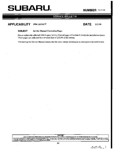
SUBARU,
APPLlCABl LlTY 1996 LEGACY DATE 2/21/96
SUBJECT Service Manual Correction Pages
Please replace the affected 1996 Legacy Service Manual pages of Section 6-2 with the included revisions.
These pages are indicated by a revision date of 2/21/96 at the bottom.
Maintaining the Service Manaul insures that the most current information is conveyed to the technicians.
VEHICLE SERVICING PERFORMED BY UNTRAINED PERSONS COULD RESULT IN SERIOUS INJURY TO THOSE PERSONS OR TO OTHERS.
Subaru Service Bulletinsare intendedfor use by professioneltechnicians ONLY. They are written to inform those technicians of conditions that may occur in some vehicles. or to provideinformationthat could assist
in the proper serviciw of the vehkle. Properly trained technicians have the equipment,tools. Safety InStrUCtiOnS,and know-howto do the lob correctly anU safely. if a conditionis described, DO NOT assumethat this
Service Bulletinapplies to your vehicle, or that your vehicle wiii have that condition.
94
SERVICE PROCEDURE [W16B4] 6-2
16. Power Window
2. SUBSWITCH
Set power window sub switch to each position and check
continuity between terminals as indicated in table below:
W
DOWN
1 0
B6M0129A
3. POWER WINDOW MOTOR
1) Make sure that power window motor rotates properly
when battery voltage is applied to terminals of motor con-
nector.
2) Change polarity of. battery connections to terminals to
ensure that motor rotates in reverse direction.
4. POWER WINDOW RELAY
Check continuity between terminals as indicated in table
below, when connecting the battery to terminal No. 1 and
No. 3,
When current flows. Between terminals Continuity exists.
No. 2 and No. 4
When current does not flow. Between terminals Continuity does not
No. 2 and No. 4 exist.
Between terminals Continuity exists.
No. 1 and No. 3
B6M0130A
95
6-2 [W17A1] SERVICE PROCEDURE
17. Power Door Lock
17. Power Door Lock
A: REMOVAL AND INSTALLATION
1. FRONT AND REAR DOOR, AND REAR GATE LOCK
ACTUATOR
Refer to 5-2 [W2A7] as for removal and installation of front
door lock actuator, rear door lock actuators, and rear
gate lock actuator.
NOTE:
To remove and install the actuators, it is necessary to dis-
assemble the door component parts.
2. DOOR LOCK TIMER
1) Remove glove box.
2) Remove back pocket cover.
3) Remove two bolts located at the rear of back pocket
cover.
4) Remove instrument panel side right cover and bolt.
5) Remove clip located at the inside end of instrument
panel.
6) Remove nut which secures door lock timer, and remove
door lock timer from bracket while pulling right side lower
end of instrument panel.
CAUTION:
Be careful not to damage instrument panel while pull-
ing its right side lower end.
7) Disconnect connector from door lock timer.
8) Installation is in the reverse order of removal.
Revised 2/21/96 96
SERVICE PROCEDURE [W18A1] 6-2
17. Power Door Lock - 18. Remote Controlled Rearview Mirror
B: INSPECTION
1. DOOR LOCK SWITCH (DRIVER'S DOOR)
-
1) Remove door trim panel.
2) Disconnect connector of door switch.
3) Set switch to each position and check continuity
between terminals as indicated in table below:
I Terminal
Switch Dosition
1
I 2
I
W0133 I UNLOCK I I
I LOCK I I I
2. ACTUATOR
1) Remove door trim panel.
2) Disconnect connector of actuator.
3) Make sure that door link moves to LOCK or UNLOCK
h-
i'
position when battery voltage is applied between terminals
as described below:
0 Connect battery positive ( + ) terminal to terminal No. 2,
and negative (-) terminal to terminal No. 4 at a moment.
0 Connect battery positive ( + ) terminal to terminal No. 4,
B6M013E and negative terminal (-) to terminal No. 2 at a moment.
18. Remote Controlled Rearview Mirror
A: REMOVAL AND INSTALLATION
1. REMOTE CONTROLLED REARVIEW MIRROR
SWITCH
1) Remove rearview mirror switch from instrument panel
by using a small standard screwdriver.
rearview mirror switch
CAUTION:
Do not pry rearview mirror switch forcefully as this may
B6M0352A
scratch instrument panel.
2) Remove rearview mirror switch while disconnecting
connector.
97
6-2 [W18A2] SERVICE PROCEDURE
18. Remote Controlled Rearview Mirror
2. REARVIEW MIRROR
1) Remove door trim panel.
2) Disconnect connector of rearview mirror.
3) Remove screws which secure rearview mirror, and then
remove rearview mi r ro r.
B6M0137
B: INSPECTION
rRearview mil`ror switch 1. REARVIEW MIRROR SWITCH
Move rearview mirror switch to each position and check
B6M0139A
1
~
3 1 I
2. REARVIEW MIRROR
Check to ensure that rearview mirror moves properly when
battery voltage is applied to terminals as indicated in table
below:
I Terminal connection I
(+I (-1
I UP I 3 I 1 I
I DOWN I 1 I 3 I
B6MO
I RIGHT I 1 I 2 I
LEFT 2 1
Revised 2/21/96 98
SERVICE PROCEDURE [W2183] 6-2
21. Cruise Control
B: REMOVAL AND INSTALLATION
1. CRUISE CONTROL MAIN SWITCH
1) Remove screws which secure meter visor.
2) Remove meter visor from instrument panel while dis-
connecting connectors.
3) Remove cruise control main switch from meter visor.
B6M0154A
2. CRUISE CONTROL COMMAND SWITCH
1) Remove screw which secures horn pad to the base of
steering wheel.
2) Remove horn pad from steering wheel while discon-
necting connector.
3) Disconnect connector of cruise control command
switch.
4) Remove screws which secure cruise control command
switch to steering wheel, and then remove command
switch.
WARNING:
Refer to 5-5 when removing or installing the module
from the airbag equipped model.
3. ACTUATOR
CAUTION:
0 Be careful not to apply excessive load to the wire
cable when adjusting and/or installing; otherwise, the
actuator may be deformed or damaged.
0 Do not bend cable sharply with a radius less than 100
mm (3.94 in); otherwise, cable may bend permanently,
resulting in poor performance.
0 When installing cable, be careful not to sharply bend
B6M015t or pinch the inner cable; otherwise, the cable may
break.
1) Loosen nut which secures cruise control cable end to
throttle cam, and then remove cable from engine throttle
cam.
2) Remove clip bands from cruise control cable.
99 Revised 2/21/96
l P + 3 f 7 - w A d In
6-2 [W2164] SERVICE PROCEDURE
21. Cruise Control
3) Remove nuts which secure actuator.
4) Remove actuator while disconnecting vacuum hose.
Tightening torque:
7.4 f7.5 N.m (0.75 f0.75 kg-m, 5.4 f 1.7 ft-l6)
4. VACUUM PUMP AND VALVES
1) Disconnect connector from vacuum pump.
2) Remove bolts which secure vacuum pump.
3) Remove A/C receiverldrier bracket.
4) Remove vacuum pump while disconnecting vacuum
hose.
Tightening torque:
7.4f 7.5 N.m (0.75 f0.75 kg-m, 5.4 f1.7 ft-16)
I B6M0359P
5. STOP AND BRAKE SWITCH
Refer to 4-5 [CIOI (MT) or C201 (AT)] as for removal and
installation of stop and brake switch.
6. CLUTCH SWITCH (MT)
Refer to 4-5 [CIOI] as for removal and installation of
clutch switch.
7. INHIBITOR SWITCH (AT)
Refer to 3-2 [W4A4] as for removal and installation of
in hibit or switch.
8. CRUISE CONTROL MODULE
1) Follow the same preparatory procedures when remov-
ing door lock timer.
2) Remove nuts which secure cruise control module, and
remove cruise control module from bracket while pulling
right side lower end of instrument panel.
CAUTION:
Be careful not to damage instrument panel while pull-
ing its right side lower end.
B6M0360A
3) Disconnect connector from cruise control module.
4) Installation is the reverse order of removal.
100
Revised 2/21/96
SERVICE PROCEDURE [W22A10] 6-2
22. Security System
8. REAR GATE SWITCH (WAGON)
NOTE:
The rear gate switch is united with the rear gate latch
assembly.
1) Remove rear gate trim panel.
2) Disconnect rod from rear gate latch assembly.
3) Disconnect rear gate switch (combined with luggage
room light switch) connector and power door lock actua-
I Latch
B6M0372P
tor connector.
4) Remove bolts which secure power door lock actuator.
5) Remove bolts which secure latch.
6) Remove latch and actuator assembly.
7) Installation is in the reverse order of removal.
Security indicator light 9. SECURITY INDICATOR LIGHT
1) Remove screws which secure meter visor.
2) Remove meter visor from instrument panel while dis-
connecting connectors.
3) Remove security indicator light from meter visor.
4) Installation is in the reverse order of removal.
B6M0373/
ecurity control module
10. SECURITY CONTROL MODULE
Steering support be 1) Follow the same preparatory procedures when remov-
Door lock timer ing door lock timer.
2) Remove nut which secures security control module,
and remove security control module from bracket while
pulling right side lower end of instrument panel.
CAUTION:
Be careful not to damage instrument panel while pull-
ing its right side lower end.
B6M0682P
3) Disconnect connector from security control module.
4) Installation is in the reverse order of removal.
101 Revised 2/21/96
lA-LIq-4- A
6-2 [W22B1] SERVICE PROCEDURE
22. Security System
B: INSPECTION
1. STARTER INTERRUPT RELAY
Battery 1) Disconnect connector of starter interrupt relay.
2) Connect battery to terminal No.1 and ground terminal
I" No. 2.
3) Check continuity between terminals as indicated in
table below:
When current flows.
When current does not flow.
t
Between terminals
No. 3 and No. 5
Between terminals
No. 3 and No. 5
Between terminals
No. 1 and No. 2
Continuity does not
Continuity exists.
Continuity exists.
B6M0375A
2. HEADLIGHT ALARM RELAY
1) Disconnect connector of headlight alarm relay.
2) Connect battery to terminal No. 1 and ground terminal
No. 2.
Battew
3) Check continuity between terminals as indicated in
table below:
When current flows. Between terminals Continuity does not
No. 3 and No. 5 exist.
Between terminals Continuity exists
No. 3 and No. 4
When current does not flow. Between terminals Continuity exists.
No. 3 and No. 5
Between terminals Continuity does not
No. 3 and No. 4 exist.
Between terminals Continuity exists.
No. 1 and No. 2
G6M0131
I
Ter m ina I
1 2
Switch position
When push rod is
pushed in.
When push rod is
0 0
B6M0376 released.
102
◦ Jabse Service Manual Search 2026 ◦ Jabse Pravopis ◦ onTap.bg ◦ Other service manual resources online : Fixya ◦ eServiceinfo