Service Manuals, User Guides, Schematic Diagrams or docs for : . Car Manuals Subaru Legacy 1995-1999 Approved Subaru Legacy 1996 1996 Tech Service Bulletin 18-29-9634441
<< Back | HomeMost service manuals and schematics are PDF files, so You will need Adobre Acrobat Reader to view : Acrobat Download Some of the files are DjVu format. Readers and resources available here : DjVu Resources
For the compressed files, most common are zip and rar. Please, extract files with Your favorite compression software ( WinZip, WinRAR ... ) before viewing. If a document has multiple parts, You should download all, before extracting.
Good luck. Repair on Your own risk. Make sure You know what You are doing.
Image preview - the first page of the document
>> Download 18-29-9634441 documenatation <<
Text preview - extract from the document
SUBARU,
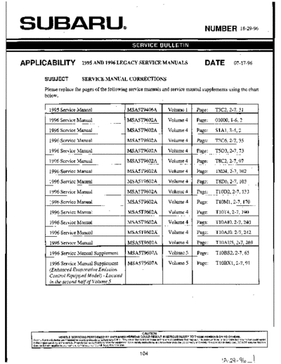
APPLlCABlLlTY 1995 AND 1996 LEGACY SERVICE MANUALS
SUBJECT SERVICE MANUAL CORRECTIONS
Please replace the pages of the following service manuals and service manual supplements using the chart
below.
1995 Service Manual MSA5T9406A Volume 1 Page: T3C2,2-7,31
1996 Service Manual MSA5T9602A Volume 4 Page: 01000, 1-6,2
1996 Service Manual MSA5T9602A Volume 4 Page: SlA1,3-4,2
1996 Service Manual MSA5T9602A Volume 4 Page: T3C6,2-7,35
1996 Service Manual MSA5T9602A Volume 4 Page: T503,2-7,73
1996 Service Manual MSA5T9602A Volume 4 Page: T8C2,2-7,97
1996 Service Manual MSA5T9602A Volume 4 Page: T8D4,2-7,102
1996 Service Manual MSA5T9602A Volume 4 Page: T8D6,2-7, 103
1996 Service Manual MSA5T9602A Volume 4 Page: TlOD2,2-7,133
1996 Service Manual MSA5T9602A Volume 4 Page: TlOM1,2-7,170
1996 Service Manual MSA5T9602A Volume 4 Page: TlOT4,2-7, 190
-
1996 Service Manual MSA5T9602A Volume 4 Page: TlOAIO, 2-7,240
1996 Service Manual MSA5T9602A Volume 4 Page: TlOAJO, 2-7,242
1996 Service Manual I MSA5T9602A I Volume 4 I Page: TlOAU5,2-7,269
I I I
1996 Service Manual Supplement MSA5T9607A Volume 5 Page: TlOBS2,2-7,65
1996 Service Manual Supplement MSA5T9607A Volume 5 Page: TlOBXl, 2-7,91
(Enhanced Evaporative Emission
Control Equipped Model) - Located
in the second half of Volume 5
CA UTI0N
VEHICLE SERVICING PERFORMED BY UNTRAINED PERSONS COULD RESULT IN SERIOUS INJURY TO THOSE PERSONS OR TO OTHERS.
Subaru Service Bulletins are intendedfor use by prolessionaltechnicians ONLY. They are written to inlOrm those technicians of conditions that may occur in some vehicles, or to provide Informationthat could assist
in the proper servicing of the vehicle. Properly trained technicians have the equipment,toois, Safety inStrUCtiOnS.and know-howto do the JobCOrreCtlY and safely. If a conditionis described, DO NOT assume that this
Service Bulletin applies to your vehicle, or that your vehicle will have that condition.
ON-BOARD DIAGNOSTICS II SYSTEM [T3C2] 2-7
Function mode Contents Abbreviation Unit of measure
F49 Intake manifold absolute pressure signal MANI. P kPa
F50 Load data (Freeze frame data) LOAD-F Yo
~ ~~~
F51 Engine coolant temperature signal (Freeze frame data) TW-F `C
F52 Short term fuel trim (Freeze frame data) ALPH-F Yo
F53 Long term fuel trim (Freeze frame data) KBLR-F %
F54
Intake manifold absolute pressure signal (Freeze frame
data)
I MANI-F I kPa
F55 Engine speed signal (Freeze frame data) EREV-F rpm
F56 Vehicle speed signal (Freeze frame data) VSP-F km/h
-
~~~~ ~~~
FA0 ON H OFF signal -
FA 1 ON H OFF sianal - -
I FA2 I ON ++ OFF signal I - I - I
-
~~ ~~
FA3 ON c) OFF signal -
FA4 ON H OFF signal - -
FBO Diagnostic trouble code (DTC) INSPECT -
FB1 Diagnostic trouble code (DTC) OBD -
FCO Clear memory - -
105
iA - 9Revised
' a - 0I, Y6
2-7 [T~C~I ON-BOARD DIAGNOSTICS II SYSTEM
3. Diagnosis System
0FUNCTION MODE: F O
O
- ROM ID NUMBER (YEAR) -
1995 CONDITION:
Ignition switch "ON"
SPECIFIED DATA:
2.2 SOHC
Presentat ion display
OBD0065
1. Error 1 -1
1
Check for loose or disconnected connector, and
discontinued circuit, etc.
0 FUNCTION MODE: FO1
- BATTERY VOLTAGE (VB) -
VB (FO1) CONDITION:
(1) Ignition switch "ON"
(2) Idling after warm-up
12.4 V
SPECIFIED DATA:
(1) l l f l v
82M0270 (2) 1 3 f l V
0 Probable cause (Item outside "specified data")
+
Check battery voltage and electrolyte's specific
gravity.
r
~
0 Check regulating voltage. (On no-load)
0 Check alternator.
3. Power supply line ~
r
0 Check main relay.
106
1/4-24
SPECIAL TOOLS 1-6
Page
1. Engine Tools ..................................................................... 2
2. Manual Transmission and Differential Tools
3. Automatic Transmission and Differential Tools
4. Rear Differential Tools (AWD Models)
5. Suspension Tools
6. Wheels and Axles Tools
7. Steering System Tools
8. Brake Tools
9. Body Tools
10. Supplemental Restraint System Tools
11. Select Monitor and Cartridge ................................................ 2
107
1-6 WO
O1 SPECIAL TOOLS
1. Enaine Tools / 11. Select Monitor and Cartridge
1. Engine Tools
499207300 498747300 498267600 ` 498267700
PISTON GUIDE CYLINDER HEAD TABLE VALVE GUIDE ADJUSTER
WRENCH
0 Used to remove and install B Used to install piston in cyl- o For replacing valve uides. Used to install intake and
lastic camshaft sprocket. inder. used to remove antinstall exhaust valve quides.
0 For DOHC engine. B For 2500 cc engine. valve springs. For DOHC engine.
o For DOHC engine.
GlH0371 GlH0143
L GlH0132
`Newly adopted tool
.
11 Select Monitor and Cartridge
498345700
CARTRIDGE
Troubleshooting for electrical
systems.
I GlH0288 I
`Newly adopted tool
108
~ ~~
AWD SYSTEM 3-4
Page
S SPECIFICATIONS AND SERVICE DATA ..................................................... 2
1. AWD System ............................................................................................ 2
C COMPONENT PARTS .................................................................................. 3
1. Rear Differential Mounting System ........................................................ 3
2. Propeller Shaft
3. Rear Differential Assembly
W SERVICE PROCEDURE
1. Propeller Shaft
2. Rear Differential
3. Rear Differential Front Member
K DIAGNOSTICS
1. Rear Differential
2. Propeller Shaft
109
6-2 [W2164] SERVICE PROCEDURE
21. Cruise Control
3) Remove nuts which secure actuator.
4) Remove actuator while disconnecting vacuum hose.
Tightening torque:
7.4 f7.5 N.m (0.75 f0.75 kg-m, 5.4 f 1.7 ft-l6)
4. VACUUM PUMP AND VALVES
1) Disconnect connector from vacuum pump.
2) Remove bolts which secure vacuum pump.
3) Remove A/C receiverldrier bracket.
4) Remove vacuum pump while disconnecting vacuum
hose.
Tightening torque:
7.4f 7.5 N.m (0.75 f0.75 kg-m, 5.4 f1.7 ft-16)
I B6M0359P
5. STOP AND BRAKE SWITCH
Refer to 4-5 [CIOI (MT) or C201 (AT)] as for removal and
installation of stop and brake switch.
6. CLUTCH SWITCH (MT)
Refer to 4-5 [CIOI] as for removal and installation of
clutch switch.
7. INHIBITOR SWITCH (AT)
Refer to 3-2 [W4A4] as for removal and installation of
in hibit or switch.
8. CRUISE CONTROL MODULE
1) Follow the same preparatory procedures when remov-
ing door lock timer.
2) Remove nuts which secure cruise control module, and
remove cruise control module from bracket while pulling
right side lower end of instrument panel.
CAUTION:
Be careful not to damage instrument panel while pull-
ing its right side lower end.
B6M0360A
3) Disconnect connector from cruise control module.
4) Installation is the reverse order of removal.
100
Revised 2/21/96
ON-BOARD DIAGNOSTICS II SYSTEM r 3 C 6 ] 2-7
3. Diagnosis System
Function mode Contents Abbreviation Unit of measure
FB1 Diasnostic trouble code (DTC) OBD -
Load data (Freeze frame data) I LOAD-F I Y
O I
Engine coolant temperature signal (Freeze frame data) TW-F "C
Short term fuel trim (Freeze frame data1 ALPH-F %
FB2 Long term fuel trim (Freeze frame data) I KBLR-F I I
Intake manifold absolute pressure signal (Freeze frame
data)
1 MANI-F kPa
I
Engine speed signal (Freeze frame data) EREV-F rPm
Vehicle speed signal (Freeze frame data) VSP-F kmlh
Mass air flow signal (Freeze frame data) QA-F (POlOO) V
Pressure sianal (Freeze frame data) I PS-F (P0105) I V I
Pressure signal (Freeze frame data) PR-F (P0106) V
Engine coolant temperature signal (Freeze frame data) TW-F (PO115) V
Throttle position signal (Freeze frame data) THV-F (PO120) V
FB3 EGR control solenoid valve signal (Freeze frame data)
I EGR (P0403) -* 1
-
Purge control solenoid valve signal (Freeze frame data) CPC (P0443) -* 1
Start switch sianal (Freeze frame data) STSW (P1100) -* 1
Pressure sources switching solenoid valve signal
(Freeze frame data)
1 BR1 (P1102) 1 -* 1
Radiator fan relay 1 signal (Freeze frame data) 1 FAN1 (P1500) I --`1 I
Clear memory - -
Compulsory fuel pump relay operation check FUEL PUMP -
I FD02
Compulsory purge control solenoid valve operation
check
1 CPCSOL -
II
Compulsory radiator fan relay operation check 1 RADFAN 1 -
ComDulsorv AIC relav ooeration check I AIC RELAY I - I
I
I
FD05 Compulsory EGR control solenoid valve operation
check
I EGRSOL I -
I
I ' FDlO
Compulsory pressure sources switching solenoid valve
operation check
-~ ~~
BR SOL -
I
NOTE:
1) Subaru select monitor is also available for monitoring
information other than that used for check and repair of
the vehicle.
2) F42 (Maximum and minimum EGR system pressure
value) will not read accurately until the EGR flow diagno-
sis terminates.
EGR flow diagnosis terminates when LED No. 2 illuminates
at function mode FA4.
3) *1: "Hi" or "Low" is shown instead of measured value.
4) Because valve is not installed, FD06, FD07, FD08, FD09
and F D l l will be displayed but non-functional.
111
I R-33- Q L 4 8 Revised 7/96
2-7 [T3C7] ON-BOARD DIAGNOSTICS II SYSTEM
3. Diagnosis System
7. FUNCTION MODE: F OO
- ROM ID NUMBER (YEAR) -
1996 CONDITION:
Ignition switch "ON"
SPECIFIED DATA:
2.2 SOHC Presentation display
B2M047C
~ ~~ ~
0 Probable cause (Item outside "specified data")
I I I ,
1. Error 1 4. Check for loose or disconnected connector, and
discontinued circuit, etc.
Check for poor contact of cartridge, or different
type cartridge.
8. FUNCTION MODE: FO1
- BATTERY VOLTAGE (VB) -
VB CONDITION:
(1) Ignition switch "ON"
(2) Idling after warm-up
12.4 V 1 SPECIFIED DATA:
(1) l l f l v
82M0270 (2) 13f:
0 Probable cause (Item outside "specified data")
1. Battery
I ~ Check battery voltage and electrolyte's specific
gravity.
4.
0 Check regulating voltage. (On no-load)
0 Check alternator.
~
0 Check main relay.
0 Check harness connector of ECM power supply
line.
112
ON-BOARD DIAGNOSTICS II SYSTEM [T503] 2-7
5. Specified Data
Connector Terminal Voltage Resistance to
Content
No. No.
Measuring conditions ,,,, bodv
I"l (ohms)
Throttle position Throttle fully closed. 0.3 - 0.7
854 8 -
sensor Throttle fully open. 4.3 - 4.9
Throttle position Ignition switch ON (with engine
sensor power 856 19
OFF) 4.8 - 5.3
..
SUDD~V . -
ATF temperature ATF temperature 20'C (68'F) 2.9 - 4.0 2.1 k - 2.9 k
854 10
sensor ATF temperature 80 ◦ Jabse Service Manual Search 2026 ◦ Jabse Pravopis ◦ onTap.bg ◦ Other service manual resources online : Fixya ◦ eServiceinfo