Service Manuals, User Guides, Schematic Diagrams or docs for : . Car Manuals Subaru Legacy 1995-1999 Approved Subaru Legacy 1996 1996 Tech Service Bulletin 18-50-9834866
<< Back | HomeMost service manuals and schematics are PDF files, so You will need Adobre Acrobat Reader to view : Acrobat Download Some of the files are DjVu format. Readers and resources available here : DjVu Resources
For the compressed files, most common are zip and rar. Please, extract files with Your favorite compression software ( WinZip, WinRAR ... ) before viewing. If a document has multiple parts, You should download all, before extracting.
Good luck. Repair on Your own risk. Make sure You know what You are doing.
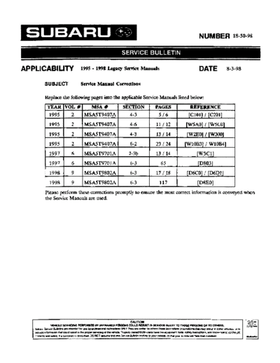
Image preview - the first page of the document
>> Download 18-50-9834866 documenatation <<
Text preview - extract from the document
NUMBER 18-50-98
APPLICABILITY -
1995 1998 Legacy Service Manuals
SUBJECT Service Manual Corrections
Replace the following pages into the applicable Service Manuals listed below:
YEAR V O L #
1995 2
MSA#
MSA5T9407A
SECTION
4-3
PAGES
516
REFERENCE
[ClOl] I [C201]
I
1995 2 MSA5T9407A 4-6 11 I 12 [W5AO] I [WSCO]
1995 2 MSA5T9407A 4-3 13 114 [W2EO] / [W300]
1995 2 MSA5T9407A 6-2 23 I 24 [W10B3] I W10B41
1997 I 6 1MSA5T9701AI 2-3b I 13 I 14 I [W3Cl]
I I I I I
1997 I
1
6 IMSA5T9701AI
I I
6-3 I 65 I [D803]
1998 1 9 IMSA5T9802AI 6-3 I 17/18 I [D6CO] I [D6D1]
I I I I I
1998 I 9 IMSA5T9802AI 6-3 117 [D8EO] I I
Please perform these corrections promptly to ensure the most correct information is conveyed when
the Service Manuals are used.
r CAUTION
VEHICLE SERVICING PERFORMED EV UwTRI)NED PERSONS COULD RESULT IN SERIOUS INJURY TO THOSE PERSONS OR TO OTHERS.
S u b m S e m Bullins am mtendecl bc use by prosssDMltechr*oans ONLY TIh?y are wtmn to mbrm moSe techrnaans of mndbonsthat may occur in SMO vehicles. or to
p m d e infamattan mat could assr5t R tlm propa sON(cII0 dtlm vehds Properlvtaned tsehrucam?have the e w e t took. safely instructnms. and know-how to do the @
q m n.
and sacek, If atmdman 6 descrlbsd DO NOT assme that tha service &Illehn appbes toyour vehcle. athat your veh&c(emH have that mndltan Ull
Il
COMPONENT PARTS [ClOl] 4-3
1. Steerina Wheel and Column (lilt)
1. Steering Wheel and Column (Tilt)
1. WITH AIRBAG MODEL
B4M1432A
(1) Bushing (7) Steering wheel lightening torque: N-m (kg-m, n-lb)
(2) Column shaft (8)' Airbag module Tl: 3.4f1.0 (0.35f0.1, 2.5f0.7)
(3) Steering roll connector (9) Plain washer T2: 25 f 5 ( . f 0.5, 1 . f 3 6
25 81 . )
(4) Column cover (10) Spring washer T3: 34 f 5 ( . f 0.5, 2 . f 3 6
35 53 . )
(5) Knee protector (11) Nut 14: 14f 5 ( . f 0.5, 3 . f 36
45 2 5 .)
(6) Bracket absorbent (12) Flange nut
Revised 07/98
4-3 tC2011 COMPONENT PARTS
2. Power Steering System
2. Power Steering System
1. LHDMODEL
lightening torque: N-m (LO-m, Il-lb) 110: 24 f 3 (2.4 f 0.3, 17.4 f 2.2)
ll: 5 . 4 f l . 5 (0.55f0.15, 4 . 0 f l . l ) 111: 24.5 f 2.0 (2.50f 0.2, 18.07f 1.48)
12: 7 . 4 f 2 . 0 (0.75*0.20, 5.4f1.4) 112: 25 f 5 (2.5 f 0.5, 18.1 f 3.6)
T3: 8 f 2 (0.8 f 0.2, 5.8 f 1.4) l l 3 : 27.0 f 2.5 (2.75 f 0.25, 19.92 f 1.84)
14: 13 f 3 (1.3 f 0.3, 9.4 f 2.2) ll4: 59 f 12 (6.0 f 1.2, 43 f 9)
T5: l 5 f 5 (1.5fO.5, 10.8f3.6) l l 5 : 60.8f6.9 (6.2f0.7, 44.8f5.1)
16: 15.7f2.4 (1.60f0.24, 11.58i1.77) 116: 78f10(8.Of1.0, 5 8 f 7 )
17: 18.1 f 2 . 5 (1.85f0.25, 13.35f1.84) ll7: 83 f 5 (8.5 f 0.5, 61-5 f 3.6)
18: 20.1 f 2 . 5 (2.05f0.25, 14.8fl.8)
19: 22 f 2 (2.2 f 0.2, 15.9 f 1.4)
SERVICE PROCEDURE Iwsrso14-6
5. Intake Door Motor
5. Intake Door Motor
A REMOVAL
1) Disconnect GND cable from battery.
2) Remove glove box and pocket back panel.
3) Remove heater duct or evaporator. (With A/C model).
4) Remove intake unit from the vehicle.
5) Remove screws which secure intake door motor to
intake unit.
NOTE:
Ensure that RECIRC switch is set to "ON".
4M1429A
Reviscd 07/98
acwxol SERVICE PROCEDURE
5. lnteke Ooor Motor
IGN B: INSPECTION
0 LHD model 1) When approx. 12 V is applied to the intake door motor
terminals, intake door motor operates as follows:
Intake
door RHD model Intake Terminal
molar door motor Intake door motor operation
position (8 Q
0 6
FRESH RECIRC
FRESH
3
' ::. Door motor moved to FRESH position.
04M0294P 2" 1'
RECIRC Door motor moved to RECIRC position.
3"
2) Connect harness to intake door motor.
3) Turn ignition switch to "ACC" and RECIRC switch to
"ON" then, set to "RECIRC".
NOTE:
Ensure that intake door motor is set in the "RECIRC"
mode.
4) Install intake door motor on intake unit.
5) Secure rod holder to link, and install link to intake unit
6) Manually set rod in the "RECIRC" mode, and secure to
rod holder.
7) Operate mode selector switch to ensure that system
changes from intake air to "RECIRC" and from "RECIRC"
to intake air in full-stroke range.
C: INSTALLATION
Installation is in the reverse order of removal
Revised 07/98
SERVICE PROCEDURE [WZEO] 4-3
2. Steering Wheel and Column
6) Align center of roll connector (with airbag model)
CAUTION:
Ensure that front wheels are set in straight-forward
direction.
7) Set steering wheel to neutral and install it onto steer-
ing shaft
CAUTION:
When using a flange nut, do not use a plain washer or
a spring washer.
Tightening torque:
0 When using plain washer, spring washer and
nut;
34 f5 N-m (3.5 f0.5 kg-m, 25.3 f3.6 ft-lb)
When using flange nut;
44 f5 N-rn (4.5 f0.5 kg-m, 32.5 f3.6 ft-lb)
Column cover-to-steering wheel clearance:
2- 4 mm (0.08- 0.16 in)
CAUTION:
Insert roll connector guide pin into guide hole on lower
end of surface of steering wheel to prevent damage.
Draw out airbag system connector, horn connector and
cruise control connectors from guide hole of steering
wheel lower end. (with airbag model)
8) Install airbag module to steering wheel (with airbag
model)
WARNING:
Always refer to 5-5 [W3Bl]i212 before performing the
service operation.
Revised 07198
4-3 [W300] SERVICE PROCEDURE
3 Steering Gearbox (Power Steering System) [LHD model]
3. Steering Gearbox (Power Steering
System) [LHD model]
NOTE:
For disassembly and assembly of gearbox unit, refer to
section Control Valve (Power Steering Gearbox).
B4M0131P
@ Cotter pin @ Orring @Valve housing
I
@ Castle nut @ Rack @ Dust seal
@ Dust cover @ Back-up washer Q Universal joint
@ Clip @ Rack housing @ washer
I
Spring
@ Tie-rod end @ Adapter lightening torque: N-m (kg-m, fi-lb)
@ Clip @ Clamp 1: 13 f 3 ( . f 0 3 9 4 f 2 2
1 13 . , . .)
@ Boot @ nut
Lock
I 1 : 24 f 3 ( . f 0 3 1 . f 2 2
2 2 4 . , 74 .)
@ Clip @ Adjusting screw 1 : 25 f 5 ( . f 0 5 1 . f 3 6
3 2 5 . , 81 . )
@ Spacer Q Spring 1 : 27.0 f 2 5
4 .
@ Tie-rod @ Sleeve
I ( . 5 f 0 2 , 1 . f 18
27 . 5 9 9 .)
@ Lock washer
I @ C-ring 75: 39 f 10 ( . f 1.O, 29 f 7
40 )
@ Circlip @ Ball bearing 1 : 59 f 72 ( . f 1 2 43f 9
6 6 0 ., )
l : 78f10(8.0f1.0,58f7)
7
0 Rack stopper @ Valve
1 : 83 f 5 ( . f 0 5 6 . f 3 6
8 85 . , 15 .)
@ Oil seal Q Seal ring
@ Rack bushing
I @ Packing
SERVICE PROCEDURE W O W 6-2
10. Front Wiper and Washer
10. Front Wiper and Washer
B: REMOVAL AND INSTALLATION
1. BLADE
Pull out blade following the arrow direction from arm while
pushing up locking clip.
2. WIPER ARM
1) Open engine hood.
2) Remove cap of wiper arm installation nut.
3) Remove the nut which secures wiper arm.
4) Remove wiper arm.
5) Installation is in the reverse order of removal.
NOTE:
Remove metal sludge from the wiper arm fixture before
installing it.
Tightening torque:
20 f 3 N.m (2.0 f 0.3 kg-m, 14.5 f 2.2 ft-16)
3. WIPER MOTOR AND LINK
1) Detach weatherstrip and cowl panel.
NOTE:
Apply silicone oil or soap water to both sides of cowl net
to facilitate removal.
2) Disconnect connector of wiper motor.
3) Remove motor attaching bolts.
Tightening torque:
5.9 f 1.5 N.m (0.6 f 0.15 kg-m, 4.3 f 1.1 ft-16)
4) Remove wiper link from back side of wiper motor using
a screwdriver inserted into service hole in front panel.
CAUTION:
Do not pry wiper link off forcefully as this may scratch
vehicle body.
5) Remove wiper motor.
6) Separate the driver's side wiper link from back side of
the passenger's side wiper sleeve unit.
Revised 07/98
6-2 I~~OB~II SERVICE PROCEDURE
10. Front Wiper and Washer
7) Remove nuts which secure sleeve unit.
Tightening torque:
5.9f1.5 N*m (0.6f0.15 kg-m, 4.3f7.1 ff-lb)
8) Remove wiper link from service hole in front panel.
4. WASHER TANK AND WASHER MOTOR
1) Remove washer tank attaching bolts.
2) Disconnect connectors of washer motors.
3) Disconnect washer hoses from each washer motor.
4) Remove washer tank and washer motor as an unit.
5) Separate washer motor from washer tank.
5. NOZZLE
1 ) Disconnect washer hose from nozzle.
2) Push nozzle clip in direction A as shown in figure.
3) Remove nozzle from engine hood.
CAUTION:
Do not pry nozzle off forcefully as this may scratch vehi-
cle body.
6. COMBlNATtON SWITCH
Refer to 6-2 [W4B3] as for removal and installation of
combination switch.
SERVICE PROCEDURE tW3Cll 2-3b
3. Camshaft
C: INSTALLATION
1. CAMSHAFT
Tightening forque: N-m (kg-m, lt-lb)
TI: 5 f 0 5 (0.5 f 0.05,36 f 0.4)
. .
12: 10f0.7 (T.OfO.07, 7.2f0.5)
13: 20 f 2 ( . f 0.2,14.5 f 1 4
20 .)
Left side cylinder head 1) Camshaft installation
Exhaust
Apply engine oil to cylinder head at camshaft bearing
h 7 7 . 5 ' \
Intake camshaft location before installing camshaft. Install camshaft so
carnshaf 110 that rocker arm is close to or in contact with "base circle"
of cam lobe.
CAUTION:
0 When camshafts are positioned as shown in figure,
camshafts need to be rotated at a minimum to align with
timing belt during installation.
0 Right-hand camshaft need not be rotated when set at
position shown in figure.
Right side cylinder head
Left-hand intake camshaft Rotate 80" clockwise.
I'\ 77 5"
Left-hand exhaust camshaft: Rotate 45" counter-clock-
Exhaust
carnshaf wise.
Revised 07/98
2-3b ~ C I I SERVICE PROCEDURE
3 Camshaft
.
2) Camshaft cap installation
(1) Apply fluid packing sparingly to cap mating sur-
face.
CAUTION:
Do not apply fluid packing excessively. Failure to do so
may cause excess packing to come out and flow toward
oil seal, resulting in oil leaks.
Fluid packing:
U (32M0752 THREE BOND 1215 or equivalent
(2) Apply engine oil to cap bearing surface and install
cap on camshaft as shown by identification mark.
(3) Gradually tighten cap in at least two stages in the
numerical order shown in figure, and then tighten to
specified torque.
(4) Similarly, tighten cap on exhaust side.
After tightening cap, ensure camshaft rotates only
slightly while holding it at "base" circle.
I G2M0753
3) Inspect for valve clearance.
Measure valve clearances using thickness gauge. < Ref.
to 2-2 [07A2].*8>
If necessary, adjust valve clearances.
4) Camshaft oil seal installation
Apply grease to new oil seal lips and press onto front end
of camshaft by using ST1 and ST2.
CAUTION:
Use a new oil seal.
ST1 499587100 OIL SEAL INSTALLER
ST2 499597000 OIL SEAL GUIDE
5) Rocker cover installation
(1) Install gaskets on rocker cover.
Install peripheral rocker cover gaskets.
(2) Apply fluid packing to four front open edges of
peripheral gasket.
Fluid packing:
THREE BOND 1215 or equivalent
( 3 ) Install rocker cover on cylinder head. Ensure gas-
ket is properly positioned during installation.
8. Electrical Wiring Harness and Ground Point
I Connector I Connecting to I
No. Pole Color Area No. Name
El 6 A3 820
2 12 Gray A-3 821 Bulkhead wiring harness
E3 16 Grav A-3 822
I E4 I 2 I Blue I A-2 1- I Purae control solenoid valve I
I E5 I 2 I Liaht aray I A-2 I Ilniector #I I
I E6 I 2 i Dark arav t A-3 I Iiniector a I
i E7 I 3 I Grav I A-3 I I Idle air control solenoid valve I
Brown 8-3 Engine coolant temperature sensor
8-3 Thermometer
El0 2 Gray 8-3 Crankshaft Dosition sensor I
E l1 1 1 8-3 Oil Dressure switch I
El2 3 Gray A-3 lanition coil I
El3 3 Brown A-3 Throttle Dosition sensor I
El4 2 Gray 8-3 Knock sensor I
El5 2 Dark gray 8-4 Camshaft Dosition sensor I
El6 2 Light gray 8-4 Injector #2
El7 2 Dark gray 8-4 Injector #4
El8 2 Brown 8-3 EGR solenoid (AT)
I Connector I Connecting to 1
I No. I Pole I Color I Area I No. I Name I
I T1 I 2 I Gray I C-1 I 824
Bulkhead wiring harness (MT)
I T2 I 2 I Brown I C-1 I 825
I T3 I 12 I Grav I 0-3 I 812
Bulkhead wiring harness (AT)
I T4 L 16 1 Grav I 0-3 I 611
I T5 I 4 I Gray I C-llC-3 I 619 IBulkhead wiring harness I
T6 4 Gray PUD-4 Rear oxygen sensor
n 12 C-4 Inhibitor switch (AT)
E: ENGINE WIRING HARNESS AN0 TRANSMISSION CORD -1
LF B6M0763
1 I 2 I 3 I 4
WlRlNG DIAGRAM trwrco] 6-3
6. Wiring Diagram
C: AIRBAG SYSTEM
To Power Supply Routing
Diagnosis
cd d & m
-
-
I I system. -
Front sub
sensor RH
(Passenger side)
sensor LH
9 @ :Airbag cord
Side airbag
sensor RH
Airbag control module
Side airbag
sensor LH
Inflator
(side LH)
6-3 [D6W WIRING DIAGRAM
6. Wiring Diagram
D: AIR CONDITIONING SYSTEM
1. LHDMODEL
A l r
conditioning @
relay holder
1O A
@A/C switch
4
I I I
M
4 - 1
1-
switch
FRESWRECIRC
actuator
Mode
actuator
Blower motor
resistor
!A:t~r~~ BmA3;;r
Iay
@(Light b lue)
BULS-02
Revised 07/98
~
I
No.
El
I
I
Connector
Pole
6
I color
I
I
1
Area
A-3
I
I
No.
820
I
Connecting to
Name I
E2 12 I Gray I A-3 1 821 Bulkhead wiring harness
E3 16 Gray A-3 822
E4 2 Blue A-2 Purge control solenoid valve
E5 2 LigM gray A-2 Injector #1
E6 2 Dark arav A-3 lniector #3
I I IIdle air control solenoid valve
~
L E7
E8
1 3
2
Gray
Brown
A-3
8-3
! Engine coolant temperature sensor
Thermometer
Crankshaft position sensor
El2 3 Gray A-3 Ignition coil
El3 3 Brown A-3 Throttle position sensor
El4 2 Gray 8-3 Knock sensor
El5 2 Darkgray 8-4 Camshaft position sensor
El6 I 2 I Light gray I 6-4 I I injector #2
El7 I 2 I Darkgray I 8-4 I Injector #4
2 I Brown 1 8-3 I IEGR solenoid (AT) I
Connector Connecting to
No. Pole Color Area No. Name
T1 2 Gray C-1 824
Bulkhead wiring harness (MT)
T2 2 Brown c-1 825
T3 12 Gray 0-3
Buikhead wiring harness (AT)
T4 16 Grav 0-3 811
T5 4 Gray C-1IG3 819 Bulkhead wiring harness
T6 4 Gray D-2/04 Rear oxygen sensor
n 12 c-4 Inhibitor switch (AT)
E: ENGINE WIRING HARNESS AN0 TRANSMISSION CORD -1
LF B6M0763
1 I 2 I 3 I 4
◦ Jabse Service Manual Search 2026 ◦ Jabse Pravopis ◦ onTap.bg ◦ Other service manual resources online : Fixya ◦ eServiceinfo