Service Manuals, User Guides, Schematic Diagrams or docs for : . Car Manuals Subaru Legacy 1995-1999 Approved Subaru Legacy 1996 1996 Tech Service Bulletin 18-53-9834868
<< Back | HomeMost service manuals and schematics are PDF files, so You will need Adobre Acrobat Reader to view : Acrobat Download Some of the files are DjVu format. Readers and resources available here : DjVu Resources
For the compressed files, most common are zip and rar. Please, extract files with Your favorite compression software ( WinZip, WinRAR ... ) before viewing. If a document has multiple parts, You should download all, before extracting.
Good luck. Repair on Your own risk. Make sure You know what You are doing.
Image preview - the first page of the document
>> Download 18-53-9834868 documenatation <<
Text preview - extract from the document
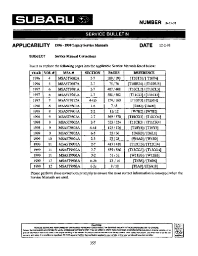
NUMBER 18-53-98
APPLICABILITY -
1996 1999 Legacy Service Manuals
SUBJECT Service Manual Corrections
Insert or replace the following pages into the applicable Service Manuals listed below:
rYEAR VOL# MSA # SECTION PAGES REFERENCE
1996 4 MSA5T9602A 2-7 1891 190 [T10T3] I [ T10T41
1996 5 MSA5T9607A 2-7 75 176 [TlOBU4] I [TlOBU5]
1997 6 MSA5T9701A 2-7 407 I408 [TlOCLZ] I [TlOCL3]
1997 6 MSAST9701A 2-7 581 I 582 [T11CI2] / [TIlCI3]
1997 7 MSA5T9712A 4-4D 159 I 160 IT10Y31 I TTlOY41
1998 I 8 MSA5T9801A 1-6 718 [OlOO] I [D400]
1998 8 MSMT9801A 2-2 11112 [W7B2] / [W7B2J
1998 9 MSA5T9802A 2-7 369 I370 [TlOC03] I [T10C04]
- 1998
- 9 MSA5T9802A 2-7 523 I 524 [T11CK31/ IT11CK41
1
1998 9 MSMT9802A 4-46 125 1126 [TlOY4] I [TlOY5]
1998 9 MSMT9802A 6-3 35 I36 [D6KO] I [D6Ll]
1999 10 MSMT9901A 2-3 27/28 [W4AO] I [W4B0]
1999 11 MSA5T9902A 2-7 417 / 418 [T12CI3] I [T12CI4]
1999 11 MSA5T9902A 2-7 559 1560 [T13CG3] I [T13CG4]
1999 11 MSA5T9902A 3-2 51 I52 [WllB3] I [WllB3]
1999 12 MSA5T9903A 6-2b 13 I14 [T6B5] I [T6B6]
1 1999 I 12 I MSA5T9903A 1 6-2c [T6A9] I [T6AlO] 1
Please perform these corrections promptly to ensure the most correct information is conveyed when the
Service Manuals are used.
355
ON-BOARD DIAGNOSTICS ll SYSTEM ~ 1 0 ~ 2-7
3 l
10. Diagnostics Chart with Trouble Code
@ : IS there poor contact in ECM connector?
@ : Repair poor contact in ECM connector.
@ : Replace ECM.
110'13 ICHECK HARNESS BETWEEN FUEL INJEC-
TOR AND ECM CONNECTOR. I
1) Turn ignition switch to OFF.
2) Disconnect connector from fuel injector on faulty cyl-
inders.
3) Measure resistance between ECM connector and
engine ground o n faulty cylinders.
: Connector termjnaf
#7 (5) No. 7 - Engine ground:
#2 (76) No. 1- Engine ground:
##3 (6) No. 7- Engine ground:
#4 (77) No. 7- Engine ground:
Is the resistance Iess than 10 0 3
@ : Repair short circuit in harness between fuel injec-
J
tor and ECM connector.
@ : Go to next step 4).
4) Measure resistance of harness connector between
ECM connector and fuel injector on faulty cylinders.
: Connector & terminal
#I (584) NO. 96 - (5) NO. 1:
#2 (B84) NO. 70 - (76) NO. 7:
#3 (584) NO. 44 - (6) NO. ':
#4 (884) NO. 76 - ( E l l ) NO. 7:
Is the resistance less than 7 Q?
: Go to step 10T4.
a : Repair open circuit in harness between ECM and
fuel injector connector.
Revised 04/98
2-7 m T]
O4 ON-BOARD DIAGNOSTICS II SYSTEM
10. Diaawtics Chart with Trouble Code
IlOT4 ICHECK FUEL INJECTOR. I
Measure resistance between fuel injector terminals on
faulty cylinder.
: Terminals
-
NO. 1 NO. 2:
ls the resistance between 5 and 20 R?
: Replace faulty fuel injector.
: Go to step 1OTS.
10T5 CHECK POWER SUPPLY LINE.
i ,
-
Revised 7/96
ON-BOARD DIAGNOSTICS ll SYSTEM 2-7
~IoBu~J
10. Diagnostics Chart with Trouble Code
,
CHECK HARNESS BETWEEN FUEL TANK
@9 10BU3 PRESSURE CONTROL SOLENOID VALVE
AND ECM CONNECTOR.
1) Turn ignition switch to OFF.
2) Disconnect connectors from fuel tank pressure control
solenoid valve and ECM.
3) Measure resistance of harness between fuel tank pres-
sure control solenoid valve connector and chassis
BZMWJOA
ground.
I I 4) Measure resistance of harness between ECM and fuel
tank pressure control solenoid valve connector.
: Connector & terminal
(884) NO. 10 - (R68) NO. 2 :
Is the resistance less than 1 R?
@ : Go to step 10BU4.
I
N
: Repair harness and connector.
NOTE:
I 62M0931A I In this case, repair the following:
0 Open circuit in harness between ECM and fuel tank
pressure control solenoid valve connector
0 Poor contact in coupling connectors (698 and R57)
CHECK FUEL TANK PRESSURE CONTROL
I
Measure resistance between fuel tank pressure control
solenoid valve terminals.
: Terminals
NO. 1 - NO. 2:
Is the resistance between 10 and 100 R?
- : G o to step 1OBUS.
I B2'~291 : Replace fuel tank pressure control solenoid valve.
Revised 11/98
2-7 vlOBU5] ON-BOARD DIAGNOSTICS II SYSTEM
10. Diagnostics Chart with Trouble Code
~~ ~~ ~
1 0 ~ ~CHECK POWER SUPPLY TO FUEL TANK
' 5
PRESSURE CONTROL SOLENOID VALVE.
ON-BOARD DIAGNOSTICS II SYSTEM ~ I O C L ~2-7
]
10. Diagnostic Chart with Trouble Code lor LHD Vehicles
1OCL1 CHECK OUTPUT SIGNAL FROM ECM.
I n I /'
@ : Go to next @
@ : Go to step 10CL2.
:Is there poor contact in ECM connector?
@ : Repair poor contact in ECM connector.
@ : Contact with SOA service.
NOTE:
Inspection by DTM is required, because probable cause is
deterioration of multiple parts.
a
CHECK HARNESS BETWEEN FUEL TANK
@9 1OCL2 PRESSURE CONTROL SOLENOID VALVE
AND ECM CONNECTOR.
1) Turn ignition switch to OFF.
2) Disconnect connectors from fuel tank pressure control
solenoid valve and ECM.
3) Measure,resistance of harness between fuel tank pres-
sure control solenoid valve connector and chassis
B2M0930A
ground.
(R68) No. 2 - Chassis ground:
Is the resistance less than 10 R?
@ : Repair ground short circuit in harness between
ECM and fuel tank pressure control solenoid
valve connector.
@ : Go to next step 4).
2-7 [TlOCL3] ON-BOARD DIAGNOSTICS II SYSTEM
10. Diagnostic Chart with Trouble Code for LHD Vehicles
4) Measure resistance of harness between ECM and fuel
tank pressure control solenoid valve connector.
@ ; Connector & terminal
-
ftl84) NO. 10 (R68) NO. 2:
Is the resistance less than 1 R?
" I I
82M0931A
: Go to step lOCL3.
@ : Repair harness and connector.
NOTE:
In this case, repair the following:
Open circuit in harness between ECM and fuel tank
pressure control solenoid valve connector
e Poor contact in coupling connectors (898 and R57)
CHECK FUEL TANK PRESSURE CONTROL
SOLENOID VALVE.
Measure resistance between fuel tank pressure control
I
solenoid valve terminals.
: Terminals
NO. 1 - NO. 2 :
Is the resistance between 70 and 700 R?
@ : G o to step 10CL4.
82M092Qf : Replace fuel tank pressure control solenoid valve.
Revised 11/98
ON-BOARD DIAGNOSTICS II SYSTEM [ T I I C I ~ I 2-7
11. Diagnostic Chart with Trouble Code for RHD Vehicles
11CI1 CHECK OUTPUT SIGNAL FROM ECM.
I
CHECK HARNESS BETWEEN FUEL TANK
11C12 PRESSURE CONTROL SOLENOID VALVE
AND ECM CONNECTOR.
(R68) No. 2 - Chassis ground:
Is the resistance less than 10 R?
Repair ground short circuit in harness between
ECM and fuel tank pressure control solenoid
valve connector.
Go to next step 4).
2-7 [TllCI3] ON-BOARD DIAGNOSTICS II SYSTEM
11. Diagnostic Chart with Trouble Code for RHD Vehicles
I I 4) Measure resistance of harness between ECM and fuel
tank pressure control solenoid valve connector.
@ : Connector 8i terminal
(884) NO. 10 - (R68) NO. 2:
Is the resistance less than 1a?
@ : G o to step 11C13.
@5J : Repair harness and connector.
NOTE:
BZMO931A In this case, repair the following:
0 Open circuit in harness between ECM and fuel tank
pressure control solenoid valve connector
0 Poor contact in coupling connectors (B97 and R57)
CHECK FUEL TANK PRESSURE CONTROL
SOLENOID VALVE.
Measure resistance between fuel tank pressure control
I
solenoid valve terminals.
@ ; Terminals
NO. 1- NO. 2:
Is the resistance between 70 and 100 R?
@ : G o to step 11C14.
82M09291 @5J : Replace fuel tank pressure control solenoid valve.
Revised 11/98
BRAKES [ABS 5.3i TYPE] FIOW 4-4d
10. Diagnostics Chart with Select Monitor
CHECK SPECIFICATIONS OF ABSCM&HIU
USING SELECT MONITOR.
1) Press [F], [O] and [O] on the select monitor.
I
2) Read the select monitor display.
: Is an ABSCM&HIU for AT model installed on
a MT model?
@ : Replace ABSCM&H/U.
@ : Go to step 10Y2.
H4M1117
1OY2 CHECK GROUND SHORT OF HARNESS.
04M1249A
I 1
10Y3 CHECK TCM.
1) Connect all connectors to TCM.
2) Turn ignition switch to ON.
3) Measure voltage between TCM connector terminal and
chassis ground.
Connector & terminal
'
~ (656) No. 5 ( )
+ - Chassis ground (-):
@ : Is the voltage more than 8.5V?
1 I ~
: Go to step ioys.
: Go to step 10Y4.
Revised 11/98
4-4d ~ 1 0 ~ 4 1 BRAKES CABS 5.31 TYPE]
10. Diagnostics Chart with Select Monitor
@ : Is the AT functioning normally?
@ : Replace TCM.
a : Repair AT.
10Y5 CHECK OPEN CIRCUIT OF HARNESS.
I
~~ ~~
10Y6 CHECK POOR CONTACT IN CONNECTORS.
10Y7 CHECK ABSCM&H/U.
' OY8 CHECK ANY OTHER TROUBLE CODES
APPEARANCE.
SPECIAL TOOLS to1w 1-6
1. Engine Took
I ILLUSTRATION TOOL NUMBER DESCRtPTioN 3EMARKS
498547000 )L FILTER WRENCH
I Jsed for removing and instailing oil filter.
499977100 :RANK PULLN I, Usedfor stoppingrotation of crankshaftpulley
YRENCH when losening and tightening crankshaft
pulley bolts.
I, ForDoHcengine.
499097600 PISTON PIN * Used for removing piston pin.
REMOVER ASSY For DOHC engine.
SHIM REPLACER KI1 Used for valve ~ j ~ t m e n t .
For DOHC engine.
(I) Replacar I (49818720)
(2) Replacer 2 (49818710)
(3) Replacer 3 (4981873Q)
Revised 11/98
1-6 [04001 SPECIAL TOOLS
4. Rear Differential Tools lAWD Models)
4. Rear Differential Tools (AWD Models)
ILLUSTRATION TOOL NUMBER DESCRIPTION 3EMARKS
398477701 4ANDLE Jsed for installing front and rear bearing cone.
B1H0230
398477702 )RIFT Jsed for press-fitting the bearing cone of differ-
Mia1 carrier (front).
398217700 4TTACHMENT SET Stand for rear differential carrier disassembly
and assembly.
BlH0143
498447120 DRIFT Used for installing front oil seal.
81H0236
498427200 FLANGE WRENCH Used for stopping rotation of companion flange
when loosening and tightening self-lock nut.
G H0224
l
SERVICE PROCEDURE fw7821 2-2
7. Valve Clearance
5) Select a shim of suitable thickness using measured valve clearance and shim thickness, using the fol-
lowing table.
intake valve {mm):S = (V + T) -C
Exhaust valve (mm): S = (V iTf -C
S: Shim thickness to be used
1
V: Measured valve clearance
T: Current shim thickness
C: Standard valve clearance
(Intake valve 0.20 +/- 0.02 mm)
(Exhaust valve 0.25 +/- 0.02mm)
6) Install selected shim and recheck valve clearance
adjustment. control solenoid valve connector.
e : Is there poor contact in ECM connec-
tor?
@ : Go to step 10C04.
@ : Repair poor contact in ECM connector.
@ : Contact with SOA service.
NOTE:
Inspection by DTM is required, because probable
cause is deterioration of multiple parts.
2-7 [TIOCO~] ON-BOARD DIAGNOSTICS II SYSTEM
10. Diagnostic Chart with Trouble Code for LHD Vehicles
10C05 : CHECK FUEL TANK PRESSURE
FUEL TANK PRESSURE CON- CONTROL SOLENOID VALVE.
TROL SOLENOID VALVE AND
ECM CONNECTOR. Measure resistance between fuel tank pressure
control solenoid valve terminals.
Measure resistance of harness between ECM and
Terminals
fuel tank pressure control solenoid valve connec-
NO. 1 - NO. 2:
tor.
Connector 8 terminal
(884) NO. 10 -
(R68) NO. 2
: m
" /r I
U
@
4
B2M093 1 A
@
B2M092f
: Is the resistance between 10 and 100
n?
8
@ : Go to step 10C06.
@ : IS the resistance less than I Q?
: Go to step 1OCO5.
a : Replace fuel tank pressure control sole-
noid valve.
@ : Repair harness and connector.
NOTE:
In this case, repair the following:
Open circuit in harness between ECM and fuel
tank pressure control solenoid valve connector
0 Poor contact in coupling connectors (B98 and
R57)
Revised 11/98
ON-BOARD DIAGNOSTICS II SYSTEM VllCKS] 2-7
11. Diaanostic Chart with Trouble Code for RHD Vehicles
11CK1 : CHECK OUTPUT SIGNAL FROM
ECM. FUEL TANK PRESSURE CONTROL
SOLENOID VALVE AND ECM CON-
1) Turn ignition switch to ON.
2) Measure voltage between ECM and chassis
ground. 1) Turn ignition switch to OFF.
2) Disconnect connectors from fuel tank pressure
Connector & terminal
(684) No. 10 (+) - Chassis ground ( )
-:
control solenoid valve and ECM.
3) Measure resistance of harness between fuel
tank pressure control solenoid valve connector and
chassis ground.
Connector & terminal
(R68) No. 2 -
Chassis ground:
: Is the voltage more than 10 V?
@ : Go to step 11CK2.
@ : Go to step 11CK3.
I11CK2 : CHECK POOR CONTACT. I @
m B2M0930/
: Is the resistance less than 10 Q?
@ : Repair ground short circuit in harness
Check poor contact in ECM connector. control solenoid valve connector.
@ : Is there poor contact in ECM connec- @ : Go to step 11CK4.
tor?
@ : Repair poor contact in ECM connector.
@ : Contact with SOA service.
NOTE:
Inspection by DTM is required, because probable
cause is deterioration of multiple parts.
2-7 FlICK4l ON-BOARD DIAG~OST~CS li SYSTEM
11. Diagnostic Chart with Trouble Code for RHD Vehicles
'
llCK5 : CHECK FUEL TANK PRESSURE
FUEL TANK PRESSURE CONTROL CONTROL SOLENOID VALVE.
SOLENOID VALVE AND ECM CON-
NECTOR. Measure resistance between fuel tank pressure
control solenoid valve terminals.
Measure resistance of harness between ECM and Teminals
fuel tank pressure control solenoid valve connec-
tor.
NO. 1 -NO. 2:
Connector & terminal
-
(B84) NO. 10 (R68) NO. 2:
B2M092S
@ : Is the resistance between 10 and 100
I 62M093 1A s23
@ : Go to step ltCK6.
: Is the resistance less than f fz? : Replace fuel tank pressure control sole-
@ : Go to step 11CK5. noid valve.
@ : Repair harness and connector.
NOTE:
In this case, repair the following:
0 Open circuit in harness between ECM and fuel
tank pressure control solenoid valve connector
Poor contact in coupling c o n n ~ t o r s
(897 and
R57)
Revised 11/98
BRAKES [ABS 5.3i TYPE] ~ I O Y ~44d
]
10. Diagnostics Chart with Select Monitor
1OY1 : CHECK SPECIFICATIONS OF THE
ABSCMCJIHIU.
lOY3 : CHECK TCM.
I
1) Connect all connectors to TCM.
Check specifications of the mark to the 2) Turn ignition switch to ON,
ABSCM&H/U. 3) Measure voltage between TCM connector ter-
minal and chassis ground.
Connector & terminal
( HNo. 5 (+)
8) - Chassis ground ( )
-:
I Mark
C1
I
1
Model
FWD AT I
I
i
c3
c4
AWD AT
AWD MT I
: IsMew~morethan6.5W?
: Is an A B S C ~ & ~ for AT
U el : Go to step lOY5.
installed on a MT model? : Go to step 10Y4.
: Replace ABSCM&H/U.
@ : Go to step 10Y2.
I10Y4 : CHECK AT. I
10Y2 : CHECK GROUND SHORT OF HAR- @ : I the AT functioning norma//y?
s
NESS. : Replace TCM.
: Repair AT.
1) Turn ignition swi?chto OFF.
2) Disconnect two connectors from TCM.
3) Disconnect connector from ABSCM&H/U.
4) Measure resistance between ABSCM&H/U
connector and chassis ground.
Connector & terminal
( F a ) No. 3 - Chassis ground:
@
@ : 1s the resistance more than 1 M Z
S?
@ : Go to step 10Y3.
@ : Repair harness between TCM and
ABSCM&H/U.
Revised 11/98
4-4d ~ I O Y ~ BRAKES [ABS 5.3i TYPE]
10. Diagnostics Chart with Select Monitor
'1OY5 : CHECK OPEN CIRCUIT OF HAR-
NESS.
' 10Y8 : CHECK ANY OTHER TROUBLE
CODES APPEARANCE.
I
- B4M1252A
: Is the voltage mom than 10 V?
: Go to step 1OY6.
@ : Repair harness/connector between AT
control module and A ~ ~ C M & ~ / U .
I10Y6 : CHECK POOR CONTACT IN CON-
NECTORS. -1
@ : Is them poor contact in connectom
between AT control module and
A B ~ ~ M O ? ~ R E W ~ R ~
& ~ ~ F
[T3Cl].fr 12,
@ : Repair connector.
@? : Go to step 10Y7.
J
~
i l O Y 7 : CHECK ABSCM&HIU. ~~ 1
Connect all connectors.
1)
Erase the memory.
2)
Perform inspection mode.
3)
Read out the trouble code.
4)
: Is the same trouble code as in the
current diagnosis still being output?
@ : Replace ABSCM&H/U.
a : Go to step 10Y8.
WlRlNG DIAGRAM [DGKO] 6-3
6. Wiring Diagram
MEMO
6-3 [D6L1] WIRING DIAGRAM
6. Wiring Diagram
L: DOOR LOCK SYSTEM
1. LHD MODEL
I, -Ref. t o Lighting system.
( i n compartment)
Ref. t o Lighting system
(Clearance & illumi.)
Security
and
keyless
entry
connector
Front door (OP)
lock actuator
-
I T
(Il@+#
I I
Door lock switch
(Passenger side) Door lock switch
Front door
lock
* 1 : Except Taiwan model
*2 :Taiwan model
a actuator
(Driver side)
Rear gate
lock
actuator
I! Rear door
lock
actuator
(Wagon)
1 I
II
II Rear door
lock
*@
*@ @*
a
(Gray)
(With
*@ @*
(Without security)
security)
m m * W i t h security :
Gray
@
(*1 - Black) (*2)
BU73-06
Revised 11/98
SERVICE P R ~ ~ E D ~ R E fw4Ao] 2-3
4. Valve Rocker Assemblv
1) Disconnect PCV hose and remove rocker
cover.
2) Removal of valve rocker assembly
(7) Remove bolts (a) through (d) in atphabetical
sequence.
CAUTION:
Leave two or three threads of bolt (a) engaged
to retain valve rocker assembly.
I
(2) Equally loosen bolts (el through (h) all the
way, be~ng careful that knock pin is not g o u g ~ .
(3) Remove valve rocker assembly.
Revised 11/98
2-3 [w4BO] SERVICE PROCEDURE
4. Valve Rocker Assembly
6: DISASSEMBLY
I (4)
(4).
82M2607A
(1) Bolt (4) Intake valve rocker arm (7) Exhaust valve rocker arm
(2) Intake valve rocker shaft (5) Spring (8) Valve rocker nut
(3) Rocker shaft support (6) Exhaust valve rocker shaft (9) Valve rocker adjust screw
1) Remove bolts which secure rocker shaft.
2) Extract rocker shaft. Remove valve rocker
arms, springs, plates and shaft supports from
rocker shaft.
CAUTION:
Arrange all removed parts in order so that they
can be installed in their original positions.
3) Remove nut and adjuster screw from valve
rocker.
ON-BOARD DIAGNOSTICS II SYSTEM 2-7
[TI~CI~]
12. Diagnostics Chart with Trouble Code for 2200 cc California Spec. LHD Vehicles
12C11 : CHECK OUTPUT SIGNAL FROM
ECM. TANK PRESSURE CONTROL
SOLENOID VALVE AND ECM CON-
1) Turn ignition switch to ON. NECTOR.
2) Measure voltage between ECM and chassis
ground. 1) Turn ignition switch to OFF.
2) Disconnect connectors from fuel tank pressure
Connector & terminal
control solenoid valve and ECM.
(8134) No. 1 (+) - Chassis ground ( )
-:
3) Measure resistance of harness between fuel
tank pressure control solenoid valve connector and
chassis ground.
Connector 8 terminal
-
(R68) No. 2 Chassis ground:
B2M2673A
: Is the voltage more than 10 V?
@ : Go to step 12C12.
@ : Go to step 12C13. B2M26741
I12C12 : CHECK POOR CONTACT. @ : Is the resistance less than 10 SZ?
@ : Repair ground short circuit in harness
Check poor contact in ECM connector. control solenoid valve connector.
@ : Is there poor contact in ECM connec- @ : Go to step 12C14.
tor?
@ : Repair poor contact in ECM connector.
@ : Contact with SOA service.
NOTE:
Inspection by DTM is required, because probable
cause is deterioration of multiple parts.
2-7 [TI~CM] ON-BOARD DIAGNOSTICS II SYSTEM
12. Diagnostics Chart with Trouble Code for 2200 cc California Spec. LHD Vehicles
12C14 : CHECK HARNESS BETWEEN FUEL 12C15 : CHECK FUEL TANK PRESSURE
TANK PRESSURE CONTROL CONTROL SOLENOID VALVE.
SOLENOID VALVE AND ECM CON-
NECTOR.
Measure resistance between fuel tank pressure
control solenoid valve terminals.
Measure resistance of harness between ECM and
Terminals
fuel tank pressure control solenoid valve connec-
NO. 1 - NO. 2:
tor.
Connector & terminal
(8134) NO. 1 -
(R68) NO. 2:
- -
@ : Is the resistance between 10 and 100
I B2M2675A R?
@ : Go to step 12C16.
@ : Is the resistance less than 1 Q?
@ : Replace fuel tank pressure control sole-
@ : Go to step 12C15. noid valve.
: Repair harness and connector.
NOTE:
In this case, repair the following:
0 Open circuit in harness between ECM and fuel
tank pressure control solenoid valve connector
0 Poor contact in coupling connectors (B98and
R57)
Revised 11/98
ON-BOARD DIAGNOSTICS li SYSTEM [T13CG3] 2-7
13. Diagnostics Chart with Trouble Code for 2200 cc California Smc. RHD Vehicles
13CG1 : CHECK OUTPUT SIGNAL FROM 13CG3 : CHECK HARNESS BETWEEN
ECM. FUEL TANK PRESSURE CON-
TROL SOLENOID VALVE AND
1) Turn ignition switch to ON. ECM CONNECTOR.
2) Measure voltage between ECM and chassis
ground. 1) Turn ignition switch to OFF.
Connector & terminal 2) Disconnect connectors from fuel tank pressure
-
(8134) No. 1 (+) Chassis ground ( )
-: control solenoid valve and ECM.
3) Measure resistance of harness between fuel
@ I tank pressure control solenoid valve connector and
chassis ground.
Connector & terminal
-
(R68) No. 2 Chassis ground:
B2M2673A
@ : Is the voltage more than 10 V?
@ : Go to step 13CG2.
@ : Go to step 13CG3. B2M2674P
113CG2 : CHECK POOR CONTACT. I : Is the resistance less than 10 527
@ : Repair ground short circuit in harness
Check poor contact in ECM connector. control solenoid valve connector.
: Is there poor contact in ECM connec- @ : Go to step 13CG4.
tor?
@ : Repair poor contact in ECM connector.
: Contact with SOA service.
NOTE:
Inspection by DTM is required, because probable
cause is deterioration of multiple parts.
2-7 [T13CG4] ON-BOARD DIAGNOSTICS II SYSTEM
13. Diagnostics Chart with Trouble Code for 2200 cc California Spec. RHD Vehicles
13CG5 : CHECK FUEL TANK PRESSURE
FUEL TANK PRESSURE CON- CONTROL SOLENOID VALVE.
TROL SOLENOID VALVE AND
ECM CONNECTOR.
Measure resistance between fuel tank pressure
control solenoid valve terminals.
Measure resistance of harness between ECM and
Terminals
fuel tank pressure control solenoid valve connec-
NO. 1 - NO. 2
:
tor.
Connector 8 terminal I I
(6134) NO. 1 -
(R68) NO. 2
:
@)
82M26761
@ : Is the resistance between 10 and 100
B2M2675A R?
: Is the resistance less than 7 SZ?
@ : Go to step 13CG6.
@ : Go to step 13CG5.
a : Replace fuel tank pressure control sole-
noid valve.
: Repair harness and connector.
NOTE:
In this case, repair the following:
0 Open circuit in harness between ECM and fuel
tank pressure control solenoid valve connector
0 Poor contact in coupling connectors (897 and
R57)
Revised 11/98
SERVICE PROCEDURE [w1163] 3-2
11. Overall Transmission
13) Take out the high clutch and reverse clutch 16) Remove snap ring and thrust needle bearing.
assembly. /
CAUTION:
Be careful not to lose thrust needle bearing.
17) Take out retaining plate, drive plate and driven
plate of 2-4 brake.
14) Take out the high clutch hub and the thrust
bearing.
18) Pull out leaf spring.
CAUTION:
Be careful not to bend leaf spring during
15) Take out the front sun gear and the thrust removal.
bearing.
Revised 11/98
3-2 [wll63] SERVICE PROCEDURE
11. Overall Transmission
19) Take out the thrust needle bearing, planetary 23) Separate 2-4 brake piston and piston retainer.
gear assembly and the low clutch assembly.
2-4 brake piston
\
RSSY and low
24) Pull out leaf spring.
20) Remove snap ring. CAUTION:
Be careful not to bend leaf spring during
removal.
f Leaf spring
Take out 2-4 brake return spring.
2-4 brake return spring
\ 25) Remove snap ring.
22) Take out 2-4 brake piston and piston retainer.
CAUTION:
When removingthe brake piston 2-4 and piston 26) Take out retai~ingplate, drive plate, driven
retainer, be careful not to rub or bump them plate and dish plate.
against the transmission case.
2-4 brake piston
/
2-4 brake piston retainer
BODY ELECTRICAL SYSTEM (KEYLESS ENTRY) mss] 6-2b
6. Diagnostics Procedure
B: DIAGNOSTICS ITEM 1
1681 : CHECK HORN OPERATION.. I
684 : CHECK HORN RELAY.
1
1) Remove horn relay.
2) Check continuity between horn relay terminals.
Press horn pad on steering wheel.
Terminals
: Does the horn sound? NO. 2- NO. 3 :
@JZ : Go to step 682.
@ : Repair Horn circuit.
I
I682 : SELECT HORN SIGNAL OPERATION. I
Keep both LOCK/ARM and UNLOCK/DISARM
buttons pressed for more than 1.5 seconds.
: Does the horn chirp one time?
@ : Go to step 683.
@GJ : Replace keyless entry control module.
: Does continuity exist?
@ : Replace horn relay.
683 : CHECK HORN SIGNAL OUTPUT SIG-'
NAL. @ : Go to step 685.
1) Disconnect connector from keyless entry con- 6B5 : CHECK HORN RELAY.
trol module.
2) Measure voltage between keyless entry control Check continui~
between horn relay terminals.
module connector (B176) and chassis ground. T8rminals
Connector & terminal NO. 1 -NO. 2:
-
(8176) No. 12 (+) Chassis ground ( )-:
: Does c
~ i
texist? ~ ~ ~ ~
: ls the voltage mom than 10 V?
@ : Go to step 6B6.
@J
Z: Go to step 684. @ : Replace horn relay.
@ : Go to step 687.
Revised 11/98
6-2b [T6B6] BODY ELECTRICAL SYSTEM (KEYLESS ENTRY)
6. Diagnostics Procedure
f6B6 : CHECK HORN RELAY. 1 688 : CHECK POWER SUPPLY FOR HORN
RELAY.
1) Connect the battery to horn relay terminals No.
1 and No. 2. Measure voltage between horn relay connector
2) Check continuity between horn relay terminals. (649) and chassis ground.
Terminals Connector & tenninal
-
NO. 2 NO. 3 : -
(649) No. 2 (+) -:
Chassis ground (1
I 1
@ : Does continuity exist? @ : Is the voltage more than 10 V?
@ : Repair wiring harness of horn circuit. @ : Go to step 6B9.
@ : Replace horn relay. @ : Repair wiring harness between horn
relay and battery.
I687 : CHECK FUSE NO. 12. I
Remove and visually check the fuse No. 12 (in fuse
box).
: Is the fuse No. I2 blown?
@ : Replace fuse (20 A).
: Go to steD 688.
Revised 11/98
BODY ELECTRICAL SYSTEM (SECURITY SYSTEM) 1 ~ 6 ~ 6-2c
91
6. Diagnostics Procedure
6. Diagnostics Procedure 6A5 : CHECK SECURITY SYSTEM FUNC-
TION.
A: BASIC DIAGNOSTICS ~
PROCEDURE 1) Press the LOCK/ARM button one time.
2) Unlock all doors with door locking switch in the
6A1 : CHECK SECURITY SYSTEM FUNC- front door.
TION. 3) Open the front left door.
1) Perform basic diagnostics procedure of keyless
e : Does the security indicator light blink
every 1 8 seconds?
1
entry system. @ : Go to step 6A6.
2) Perform pre-inspection.
@ : Go to step 6D1.
3) Open all windows. 6A6 : CHECK SECURITY SYSTEM FUNC-
4) Remove ignition key from ignition switch. TION.
5) Set the room light switch in the middle position.
6) Close all doors, rear gate and trunk lid.
7) Press the LOCK/ARM button one time. Check if the clearance light activates.
@ : Does the clearance light blink one : Does the clearance light blinking
time? remain?
@ : Go to step 6A7.
@ : Go to step 6A2.
@ : Replace security control module.
@ : Go to step 661.
6A2 : CHECK SECURITY SYSTEM FUNC- 6A7 : CHECK SECURITY SYSTEM FUNC-
TION. TION.
Check if the security indicator light blinks. Check if the horn activates.
@ : Does the security indicator light blink
every 2 seconds?
e : Does the horn sound remain?
@ : Go to step 6A8.
@ : Go to step 6A3.
@ : Replace security control module.
@ : Go to step 6C1.
6A3 : CHECK SECURITY SYSTEM FUNC-
TION. I 6A8 : CHECK SECURITY SYSTEM FUNC-
TION.
Press the UNLOCK/DISARM button one time. Turn on starter.
@ : Does the clearance light blink two @ : Does the starter motor activate?
times?
@ : Go to step 6E1.
@ : Go to step 6A4. @ : Go to step 6A9.
@ : Replace security control module.
1 6 ~ :9 CHECK SECURITY SYSTEM FUNC-
TION.
I 6A4 : CHECK SECURITY SYSTEM FUNC-
TION. Close the front left door.
@ : Does the horn sound and clearance
Check if the room light activates. light blinking deactivate, and starter
@ : Does the room light turn on for 30 motor activate after approximately 30
seconds, and then turn off? seconds?
@ : Go to step 6A5. @ : Go to step 6A10.
@ : Replace security control module. @ : Replace security control module.
Revised 11/98
6 - 2 [T~AIO] BODY ELECTRICAL SYSTEM (SECURITY SYSTEM)
~
6. Diagnostics Procedure
6A10 : CHECK SECURITY SYSTEM FUNC- 6A14 : CHECK SECURITY SYSTEM FUNC-
TION. TION.
Check if the security indicator light activates. 1) Close the rear left door.
: Does the security indicator light blink 2) Open the rear right door.
every 2 seconds? @ : Does the security indicator light blink
@ : Go to step 6A11. every 1 8 seconds, the horn sound,
1
the clearance light blink, and the
@ : Replace security control module. starter motor deactivate?
.
@ : Go to step 6A15.
I
6A11 : CHECK SECURITY SYSTEM FUNC-
TION. I @ : Go to step 6H1.
I6A15 : CHECK SECURITY SYSTEM FUNC- I
Open the front right door.
@ :
TION.
I
@ :
a:
6A16 : CHECK SECURITY SYSTEM FUNC-
6A12 : CHECK SECURITY SYSTEM FUNC- TION.
"
Press the UNLOCIUDISARM button. : Does the security indicator light blink
@ : Does the security indicator light every 1 8 seconds, the horn sound,
1
blink, the horn and clearance light the clearance light blink, and the
deactivate, and the starter motor acti- starter motor deactivate?
vate? @ : Go to step 6Ai8.
@ : Go to step 6A13. @ : Go to step 611.
@ : Replace security control.module.
f6A17 : CHECK SECURITY SYSTEM FUNC- 1
I TION.
I 6A13 : CHECK SECURITY SYSTEM FUNC-
TION. I Open the trunk lid.
@ : Does the security indicator light blink
1) Close the front right door. every 118 seconds, the horn sound,
2) Press the LOCWARM button. the clearance light blink, and the
3) Open the rear left door. starter motor deactivate?
@ : Does the security indicator light blink
@ : Go to step 6A18.
every 1/8 seconds, the horn sound,
: Go to step 6J1.
the clearance light blink, and the
starter motor deactivate?
@ : Go to step 6A14.
@ : Go to step 6G1.
◦ Jabse Service Manual Search 2026 ◦ Jabse Pravopis ◦ onTap.bg ◦ Other service manual resources online : Fixya ◦ eServiceinfo