Service Manuals, User Guides, Schematic Diagrams or docs for : . Car Manuals Subaru Legacy 1995-1999 Approved Subaru Legacy 1997 1997 Service Manual 1997 LEGACY MANUAL SUPPLEMENT ABS 5.3I SYSTEM Mechanical Components Section MSA5T9712A29590
<< Back | HomeMost service manuals and schematics are PDF files, so You will need Adobre Acrobat Reader to view : Acrobat Download Some of the files are DjVu format. Readers and resources available here : DjVu Resources
For the compressed files, most common are zip and rar. Please, extract files with Your favorite compression software ( WinZip, WinRAR ... ) before viewing. If a document has multiple parts, You should download all, before extracting.
Good luck. Repair on Your own risk. Make sure You know what You are doing.
Image preview - the first page of the document
>> Download MSA5T9712A29590 documenatation <<
Text preview - extract from the document
4-4       LM13-1]                                       BRAKES
13. Anti-lock Brake System (ABS) [5.3i Type]


13 . Anti-lock Brake System (ABS) [5 .3i Type]
1 . FEATURE
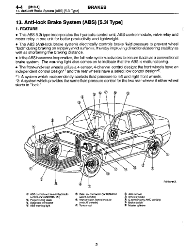
* This ABS 5.3i type incorporates the hydraulic control unit, ABS control module, valve relay and
motor relay in one unit for better productivity and lightweight .
* The ABS (Anti-lock brake system) electrically controls brake fluid pressure to prevent wheel
"lock" during braking on slippery road surfaces, thereby improving directional/steering stability as
well as shortening the braking distance .
* If the ABS becomes inoperative, the fail-safe system activates to ensure it acts as a conventional
brake system . The warning light also comes on to indicate that the ABS is malfunctioning .
" The front-and-rear wheels utilize a 4-sensor, 4-channel control design : the front wheels have an
independent control design*1 and the rear wheels have a select low control design*2 .
*1 : A system which independently controls fluid pressure to left and right front wheels .
*2 : A system which provides the same fluid pressure control for the two rear wheels if either wheel
starts to "lock."


                                                                                                                       ?15A


        10 ABS control module and hydraulic   OO Data link connector (for SUBARU   OO ABS sensor
           control unit (ABSCM&H/U)              select monitor)                   09    Wheel cylinder
           Proportioning valve                OO Transmission control module       O     G sensor (only AWD vehicle)
       OO Diagnosis connector                    (only AT vehicle)                  >>   Brake switch
       OO ABS warning light                      Tone wheel                        D     Master cylinder


                                                              2
                                                    BRAKES                                              IM13-21     4-4
                                                                           13 . Anti-lock Brake System (ABS) [5.3i Type]


2. FUNCTIONS OF SENSORS AND ACTUATORS

                      Name                                                         Function

ABS control module and hydraulic   ABSCM-         e Calculates and determine the conditions of the wheels and body from
control unit (ABSCM&H/U)           section        the wheel speeds and makes a proper decision suitable for the current
                                                  situation to control the hydraulic unit.
                                                     In the ABS operation mode, the module outputs a cooperative control
                                                  signal to the AT control module . (AT vehicles only)
                                                     Whenever the ignition switch is placed at ON, the module makes a
                                                  self diagnosis. When anything wrong is detected, the module cuts off
                                                  the system .
                                                     Communicates with the Subaru select monitor.

                                   H/U-section    In the ABS operation mode, the H/U changes fluid passages to control
                                                  the fluid pressure of the wheel cylinders in response to an instruction
                                                  from the ABSCM.
                                                  The H/U also constitutes the brake fluid passage from the master cylin-
                                                  der to the wheel cylinders together with pipings.

                                   Valve relay-   Serves as a power switch for the solenoid valve and motor relay coil in
                                   section        response to an instruction from the ABSCM.

                                   Motor relay-   Serves as a power switch for the pump motor in response to an instruc-
                                   section        tion from the ABSCM.

Wheel speed sensor (ABS sensor)                   Detects the wheel speed in terms of a change in the magnetic flux den-
                                                  sity passing through the sensor, converts it into an electrical signal, and
                                                  outputs the electrical signal to the ABSCM.

Tone wheel                                        Gives a change in the magnetic flux density by the teeth around the tone
                                                  wheel to let the ABS sensor generate an electrical signal .

G sensor (AWD vehicle only)                       Detects a change in G in the longitudinal direction of the vehicle and
                                                  outputs it to the ABSCM in terms of a change in voltage.

Stop light switch                                 Transmits the information on whether the brake pedal is depressed or
                                                  not to the ABSCM for use as a condition in determining ABS operation.

ABS warning light                                 Alerts the driver to an ABS fault. When the diagnosis connector and
                                                  diagnosis terminal are connected, the light flashes to indicate a trouble
                                                  codes in response to an instruction from the ABSCM.

AT control module (TCM) (AT vehicles only)        Provides shift controls (fixing the speed at 3rd or changing front and rear
                                                  wheel transmission characteristics on 4WD vehicle) in response to an
                                                  instruction from the ABSCM.
4-4     [M13-21                                       BRAKES
13. Anti-lock Brake System (ABS) [5.3i Type]


                                                                                      O


 BATTERY


                                                                                                                B4H1216A


         O ABS control module and              S  Front right outlet solenoid valve   D    ABS warning light
           hydraulic control unit              (2 Rear left inlet solenoid valve'     0    Stop light switch
         9 ABS control module section          D  Rear left outlet solenoid valve     0    Stop light
           Valve relay                         0  Rear right inlet solenoid valve     (5   G sensor (only AWD model)
         O Motor relay                         8  Rear right outlet solenoid valve    0    Front left ABS sensor
         m Motor                               R  Transmission control module         Z    Front right ABS sensor
           Front left inlet solenoid valve        (only AT module)                    Z    Rear left ABS sensor
         8 Front left outlet solenoid valve    (3 Diagnosis connector                 (8   Rear right ABS sensor
           Front right inlet solenoid valve    0 Data link connector
                           BRAKES                               [M13-4]     4-4
                                    13. Anti-lock Brake System (ABS) [5.3i Type]


3. THEORY OF ABS CONTROL
Refer to 4-4 [M8-3] .*1

4. ABS SENSOR
Refer to 4-4 [M8-4] .*1
4-4     [M13-51                                BRAKES
13. Anti-lock Brake System (ABS) [5.3i Type]


5. ABS CONTROL MODULE AND HYDRAULIC CONTROL UNIT (ABSCM&H/U)
* ABS CONTROL MODULE SECTION (ABSCM)
The ABSCM is a digital control type electronic control module accommodating two microcontrol
modules (MCMs) ; master and slave . Both MCMs process the same program and monitor the
respective outputs, and when a mismatch occurs, cut off the system to activate the fail-safe func-
tion .
A maximum of 3 trouble codes are stored in the EEP ROM and if 3 or more areas fail, then only the
3 most recent failures are stored . The trouble codes remain stored until they are erased .
This ABSCM induces a sequence control pattern and facilitates the checking of the hydraulic unit.
" ABS control
Based on the four wheel speed signals, the ABSCM calculates a simulated body speed or body
deceleration rate, while referencing the G sensor output as an auxiliary means, and compares
them with the wheel speeds and wheel deceleration rates . If it determines that the wheels are
about to lock, it controls the solenoid valve or motor pump of the H/U to adjust the brake fluid pres-
sures that act on the wheel cylinders, thereby preventing the wheels from locking .
The ABSCM controls the right and left front wheel fluid pressures independently and controls the
rear wheel fluid pressures on the basis of the wheel which is more likely to lock (Select-low control) .
" Select monitor associated functions
The Subaru select monitor may be used to perform the following operations .
O To read out analog data
       To read out ON/OFF data
O To read out or erase trouble code
O To read out status information in the event of trouble (Freeze frame data)
O To initiate ABS sequence control pattern
" Indication functions
The ABS warning light can be made to indicate the following three states .
O ABS trouble
       Flashes to indicate trouble codes in diagnosis mode.
O Valve ON/OFF when sequence control pattern is in effect


                                                   6
                                            BRAKES                                       [M13-5]     4-4
                                                             13. Anti-lock Brake System (ABS) [5.3i Type]


 " HYDRAULIC CONTROL UNIT SECTION (H/U)
The H/U is a fluid pressure controller comprising a motor, solenoid valve, housing, relay, etc . It
constitutes two diagonally independent brake fluid circuits for a cross piping vehicle .
" The pump motor rotates an eccentric cam to let the plunger pump generate a hydraulic pres-
sure.
" The housing accommodates the pump motor, solenoid valve, reservoir, etc., and also consti-
tutes a brake fluid passage .
" The plunger pump is a hydraulic pump which drains off the brake fluid which, when the pressure
is reduced, is discharged to the reservoir, and sends it toward the master cylinder.
" The solenoid valve is a 2-position type solenoid valve which switches the brake fluid passages
between the wheel and master cylinder and reservoir sides in response to an instruction from the
ABSCM.
For each wheel cylinder, a pair of normally-closed and -opened solenoid valves are provided .
* The inlet solenoid valve is duty-controlled to reduce brake fluid pulsation for IowerABS operation
noise .
" The reservoir is a fluid chamber which temporarily stores the brake fluid to be discharged from
the wheel cylinder when the pressure is reduced .
" The damper chamber suppresses the pulsation of the brake fluid which, when the pressure is
reduced, is discharged from the plunger pump, thereby minimizing the kickbacks to the brake
pedal.
* The valve relay controls the solenoid valve and motor relay energizing power supply in response
to an instruction from the ABSCM. In normal (1G ON) condition, the relay is actuated to supply
power to the solenoid valve and motor relay. When an error occurs in the system, the valve relay
is forced to OFF to keep the fluid pressure circuit in the normal mode (normal brake mode) and
also constitute the ABS warning light operating circuit.
" The motor relay supplies power to the pump motor to operate the plunger pump in response to
an instruction from the ABSCM in the ABS control mode .

The H/U has four operating modes ; normal mode (control OFF : normal brake mode), "increase",
"hold" and "decrease" modes (control ON in all the three modes) .


                                                 7
4-4     [M13-51                                    BRAKES
13. Anti-lock Brake System (ABS) [5.3i Type]


1) During normal braking (Explained with one wheel's control as an example)
Since no current is supplied to the inlet and outlet solenoid valves, no solenoid valve attracting
force is generated . So the valves remain stationary.
Accordingly, the inlet port of the inlet solenoid valve is in an opened state, whereas the outlet port
of the outlet solenoid valve is in a closed state . So the fluid pressure of the master cylinder is trans-
mitted to the wheel cylinder to produce a brake force in the wheel cylinder.


                                            v
                     From master cylinder


               N


              Du


                                            Reservoir


                                                                                                 B4H0989
                                                      BRAKES                                [M13-5]     4-4
                                                                13. Anti-lock Brake System (ABS) [5.3i Type]


2) Pressure "decrease" action with ABS in operation (Explained with one wheel's control
as an example)
Current is supplied to the inlet and outlet solenoid valves, and the generated solenoid valve attract-
ing forces close the inlet port and open the outlet port .
Accordingly, the wheel cylinder is isolated from the master cylinder and becomes clear to the res-
ervoir, allowing the brake fluid to flow to the reservoir. So the fluid pressure of the wheel cylinder
is decreased .
The brake fluid collected in the reservoir is fed to the master cylinder by the pump .


                   From master cylinder   \ /
                                           \/


                                                Reservoir


                                                                                                  B4H0990


                                                            9
4-4       IM13-5]                                     BRAKES
13. Anti-lock Brake System (ABS) [5.3i Type]


3) Pressure "hold" action with ABS in operation (Explained with one wheel's control as an
example)
Current is supplied to the inlet solenoid valve, and the generated solenoid valve attracting force
closes the inlet port.
Since no current is supplied to the outlet solenoid valve, the output port remains in a closed state .
As a result, the wheel cylinder, master cylinder and reservoir are blocked, and the fluid pressure
of the wheel cylinder is maintained constant .
During ABS operation, the pump motor continues to operate .


                         From master cylinder
                                                N~


                  O


                                                 Reservoir


                                                                                               B4H0991


                                                             10
                                                    BRAKES                                  [M13-5]     4-4
                                                                13. Anti-lock Brake System (ABS) [5.3i Type]


4) Pressure "increase" action with ABS in operation (Explained with one wheel's control as
an example)
Since no current is supplied to the inlet and outlet solenoid valves, no solenoid valve attracting
force is generated . So the valves remain stationary .
Accordingly, the inlet port of the inlet solenoid valve is in an opened state, whereas the outlet port
of the outlet solenoid valve is in a closed state. So the fluid pressure of the master cylinder is trans-
mitted to the wheel cylinder to increase the brake force in the wheel cylinder.
During ABS operation, the pump motor continues to operate.


                       From master cylinder   \
                                               V


                                                   Reservoir


                                                                                                  B4H0992


                                                          11
4-4      [M13-6l                                 BRAKES
13. Anti-lock Brake System (AB S) [5.3 i Type]


6. ABS CONTROL CYCLE CURVES
Refer to 4-4 [M8-6] -*1

7 . ABS WARNING LIGHT
Refer to 4-4 [M8-7] -*1

S. G SENSOR
Refer to 4-4 [M12-8] .*5


                                                   12
◦ Jabse Service Manual Search 2026 ◦ Jabse Pravopis ◦ onTap.bg ◦ Other service manual resources online : Fixya ◦ eServiceinfo