Service Manuals, User Guides, Schematic Diagrams or docs for : . Car Manuals Subaru Legacy 1995-1999 Approved Subaru Legacy 1997 1997 Service Manual 1997 LEGACY MANUAL SUPPLEMENT ABS 5.3I SYSTEM Diagnostics Section MSA5T9712A29605
<< Back | HomeMost service manuals and schematics are PDF files, so You will need Adobre Acrobat Reader to view : Acrobat Download Some of the files are DjVu format. Readers and resources available here : DjVu Resources
For the compressed files, most common are zip and rar. Please, extract files with Your favorite compression software ( WinZip, WinRAR ... ) before viewing. If a document has multiple parts, You should download all, before extracting.
Good luck. Repair on Your own risk. Make sure You know what You are doing.
Image preview - the first page of the document
>> Download MSA5T9712A29605 documenatation <<
Text preview - extract from the document
4-4d [T1 0A01 BRAKES [ABS 5.3i TYPE]
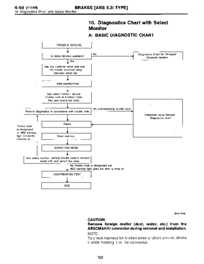
10 . Diagnostics Chart with Select Monitor
10. Diagnostics Chart with Select
Monitor
A: BASIC DIAGNOSTIC CHART
I TROUBLE OCCURS. I
No Diagnostics Chart for On-board
Is Select Monitor available?
Diagnosis System
Yes
Ask the customer when and how
the trouble occurred using
interview check list .
I PRE-INSPECTION I
Use select monitor, retrieve
trouble code in function mode
FBi and record the code.
No corresponding trouble code
Perform diagnostics in accordance with trouble code .
Inspection using General
Diagnostics chart
Repair.
Trouble code
is designated
or ABS warning
light constantly Clear memory.
remains on .
I INSPECTION MODE I
Use select monitor, retrieve trouble code in function
model FB1 and record the code .
No trouble code is designated and
ABS warning light goes out after turning on .
I CONFIRMATION TEST I
END
B4M1076A
CAUTION:
Remove foreign matter (dust, water, etc.) from the
ABSCM&H/U connector during removal and installation .
NOTE :
To check harness for broken wires or short circuits, shake
it while holding it or the connector.
102
BRAKES [ABS 5.31 TYPE] [T10B0] 4-4d
10 . Diagnostics Chart with Select Monitor
B: LIST OF TROUBLE CODE
Code Display screen (FBi) Contents of diagnosis Ref. to
- ERROR 3 (1) Select monitor communication failure [T10COJ*10
Although no trouble appears on the select monitor display, the ABS
11 NO TROUBLE [T10D0]*10
warning light remains on .
21 FR . SS HARD Open circuit or input voltage too high of FR sensor [T10E0]*10
22 FR . SS SOFT Abnormal ABS sensor signal of FR sensor [T1010J*10
23 FL . SS HARD Open circuit or input voltage too high of FL sensor [T10F0]*10
24 FL . SS SOFT Abnormal ABS sensor signal of FL sensor [T10J0]*10
25 RR . SS HARD Open circuit or input voltage too high of RR sensor [T10G0]*10
26 RR . SS SOFT Abnormal ABS sensor signal of RR sensor [T10K0]*10
27 RL. SS HARD Open circuit or input voltage too high of RL sensor [T10H0]tr10
28 RL. SS SOFT Abnormal ABS sensor signal of RL sensor [T10L0]*10
29 EITHER . SS SOFT Abnormal ABS sensor signal (any one of four) JT10M0]{r10
31 FR . EV VALVE Abnormal FR inlet valve [T10N0]*10
32 FR . AV VALVE Abnormal FR outlet valve [T10R0]*10
33 FL. EV VALVE Abnormal FL inlet valve [T1000]*10
34 FL . AV VALVE Abnormal FL outlet valve [T10S0]xr10
35 RR . EV VALVE Abnormal RR inlet valve [T10P0]*10
36 RR . AV VALVE Abnormal RR outlet valve [T10T0]*10
37 RL . EV VALVE Abnormal RL inlet valve [T10QO]*10
38 RL . AV VALVE Abnormal RL outlet valve [T10U0]tr10
41 ECU Abnormal ABSCM&H/U [T10V0)*10
LOW VOLTAGE Source voltage is low. [T10W0]tr10
42
HIGH VOLTAGE Source voltage is high . [T10X0]*10
CCM LINE A combination of AT control abnormals (ABS not in control) [T10Y0]*10
44
CCM OPEN A combination of AT control abnormals (ABS in control) [T10Z0]*10
V. RELAY Abnormal valve relay [T10AA0]*10
51
V. RELAY ON Valve relay ON failure [T10AB0]*10
M. RELAY OPEN Open circuit of motor relay [T10AC0]*10
52 M. RELAY ON Motor relay ON failure [T10AD0]tr10
MOTOR Abnormal motor [T10AE0]*10
54 BLS Abnormal stop light switch [T10AF0]*10
G SENSOR LINE Open or short circuit of G sensor [T10AG0]*10
G SENSOR +B Battery short of G sensor [T10AH0]*10
56
G SENSOR H ~x Abnormal G sensor high V output [T10A10]*10
G SENSOR STICK I G sensor output is stuck. [T10AJ0]*10
NOTE :
High ~t means high friction coefficient against road
surface.
103
4-4d [Tioco] BRAKES [ABS 5.31 TYPE]
10. Diagnostics Chart with Select Monitor
C: ERROR 3 (1)
- SELECT MONITOR COMMUNICATION
FAILURE -
*~k*~k~~*~k***~k~k~k DIAGNOSIS :
Faulty harness connector
ERROR 3 TROUBLE SYMPTOM :
" ABS warning light remains on .
84M0943
" ERROR 3 or 1 appears on the select monitor display.
WIRING DIAGRAM:
F49 f2 8100 IGN sw
Fuse S8F-4 FL1 .258
o-
No .18
818
Data link
ABS connector
control
module
and
hydraulic
control
unit
Generator
8100 878 F49
1 12 13 14 15 1 61 7 1 8 19 110 111 112113 1415
4 9 11 16 117 118119 12012 1 2 23 4 25 96
5 26
1 1 1 1 41 1 1 9 0 ~0L_LLl~J 128 29 30 31
84M1266
104
BRAKES [ABS 5.3i TYPE] [T10C4] 4-4d
10 . Diagnostics Chart with Select Monitor
1 10C1 I CHECK GENERATOR. I
1) Start the engine.
1~ \
2) Idle the engine.
3) Measure voltage between generator and chassis
v ILIA ground .
Terminal
Generator B terminal (+) - Chassis ground ():
J % m(l (l n !~ 5r CHECK ; Is the voltage between 10 and 15 V?
B4M0430
Go to step 10C2.
No : Repair generator .
10C2 CHECK BATTERY TERMINAL .
Turn ignition switch to OFF.
CHECK : Is there poor contact at battery terminal?
,rES : Repair battery terminal.
No : Go to step 10C3 .
10C3 CHECK MMUNICATION OF SELECT
I MONITOR .
Using the select monitor, check whether communication
to other system (such as engine, AT, etc.) can be executed
normally .
CHECK : Are the name and year of the system dis-
played on the select monitor?
Go to step 10C4.
No : Repair select monitor communication cable and
connector.
10C4 CHECK INSTALLATION OF ABSCM&H/U
I CONNECTOR.
Turn ignition switch to OFF.
CHECK : Is ABSCM&HIU connector inserted into
ABSCM&HlU until the clamp locks onto it?
Go to step 10C5.
n~o : Insert ABSCM&H/U connector into ABSCM&H/U
until the clamp locks onto it.
105
4-4d [T1ocs1 BRAKES [ABS 5.3i TYPE]
10 . Diagnostics Chart with Select Monitor
I 10C5 I CHECK POWER SUPPLY OF ABSCM&H/U .
1) Disconnect connector from ABSCM&H/U .
2) Start engine.
3) Idle the engine .
4) Measure voltage between ABSCM&H/U connector and
chassis ground .
Connector & terminal
(F49) No. 1 (+) - Chassis ground ():
CHECK ; Is the voltage between 10 and 15 V?
,rES : Go to step 10C6 .
No : Repair ABSCM&H/U power supply circuit.
I 10C6 I CHECK GROUND CIRCUIT OF ABSCM&H/U.
F49
1) Turn ignition switch to OFF.
1 2 3L415161718 9 110 111 112 1131 14115
6171819 2 21 2) Measure resistance between ABSCM&H/U connector
I U 23 24 25 26
712 8121301311 and chassis ground .
Connector & terminal
(F49) No. 23 - Chassis ground:
D ~ CHECK ; Is the resistance less than 0.5 0?
SC
B4M 1243A
Repair harness/connector between ABSCM&H/U
and select monitor.
No : Go to step 10C7 .
106
BRAKES [ABS 5.31 TYPE] [710C8] 4-4d
10 . Diagnostics Chart with Select Monitor
1
2 3 4 5
(~◦ Jabse Service Manual Search 2026 ◦ Jabse Pravopis ◦ onTap.bg ◦ Other service manual resources online : Fixya ◦ eServiceinfo