Service Manuals, User Guides, Schematic Diagrams or docs for : . Car Manuals Subaru Legacy 1995-1999 Approved Subaru Legacy 1997 1997 Service Manual 1997 LEGACY MANUAL SUPPLEMENT ABS 5.3I SYSTEM Diagnostics Section MSA5T9712A29600
<< Back | HomeMost service manuals and schematics are PDF files, so You will need Adobre Acrobat Reader to view : Acrobat Download Some of the files are DjVu format. Readers and resources available here : DjVu Resources
For the compressed files, most common are zip and rar. Please, extract files with Your favorite compression software ( WinZip, WinRAR ... ) before viewing. If a document has multiple parts, You should download all, before extracting.
Good luck. Repair on Your own risk. Make sure You know what You are doing.
Image preview - the first page of the document
>> Download MSA5T9712A29600 documenatation <<
Text preview - extract from the document
4-4d [TSOi1                             BRAKES [ABS 5.31 TYPE]
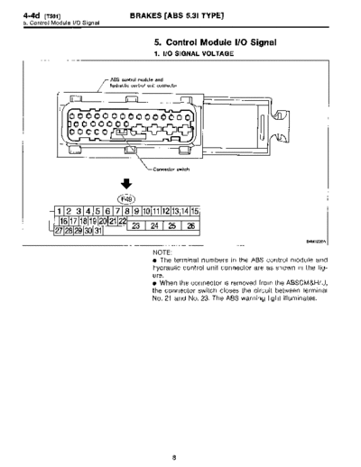
5. Control Module I/O Signal


                                                    5. Control Module I/O Signal
                                                   1 . I/O SIGNAL VOLTAGE


                               ABS control module and
                               hydraulic control unit connector


                                      Ell

                30000000
                00000


                                                   Connector switch


                                   i
                                    F49
            1 21314 5 1 6 1 7 1 8 1 9 110 1 11 1 12 113 1 14 115
             16 171819 20 2122
         1 27128 129 130 1 31 1    23     24 25             26
                                                                                                     84M1228A


                                                   NOTE :
                                                   * The terminal numbers in the ABS control module and
                                                   hydraulic control unit connector are as shown in the fig-
                                                   ure.
                                                   9 When the connector is removed from the ABSCM&H/U,
                                                   the connector switch closes the circuit between terminal
                                                   No. 21 and No . 23. The ABS warning light illuminates.


                                                            8
                                            BRAKES [ABS 5.31 TYPE] '                                                [T501] 4-4d
                                                                                                      5. Control Module I/O Signal


                                                     Terminal                              Input/Output signal
 Contents                                               No .
                                                                               Measured value and measuring conditions
                                                              _)

 ABS              Front left wheel                    9-10
 sensor'2         Front right wheel                   11-12                                    0 .12 - 1 V
 (Wheel
                  Rear left wheel                      7-8                                  (When it is 20 Hz .)
 speed
 sensor)          Rear right wheel                    14-15

 Valve relay power supply                             24-23                       10 - 15 V when ignition switch is ON .

 Motor relay power supply                             25-23                       10 - 15 V when ignition switch is ON .

                  Power supply                        30-28                                   4 .75 - 5 .25 V
 G sensor'2
 (AWD model    ground                                   28                                          -
 only)
               output                                 6-28                  2 .3f0.2 V when vehicle is in horizontal position .

                                                                       Less than 1 .5 V when the stop light is OFF and, 10 - 15 V
 Stop light switch*1                                  2-23
                                                                                        when the stop light is ON.

                                                                       Less than 1 .5 V during 1 .5 seconds when ignition switch is
 ABS warning light`2                                  21-23
                                                                                 ON, and 10 - 15 V after 1 .5 seconds .

 AT ABS signal'2                                                       Less than 1 .5 V when the ABS control does not operate still
                                                      31-23
 (AT model only)                                                                and more than 5 .5 V when ABS operates .

                                                                       Less than 1 .5 V when the ABS control does not operate still
 ABS operation signal monitor*2                       3--23
                                                                                and more than 5 .5 V when ABS operates .

 Select        Data is received .                     20-23                    Less than 1 .5 V when no data is received .
 monitor'2     Data is sent .                         5--23                       4 .75 - 5 .25 V when no data is sent .

 ABS           Terminal No . 3                        29-23                      10 - 15 V when ignition switch is ON .
 diagnosis
 connector*2   Terminal No . 6                        4-23                       10 - 15 V when ignition switch is ON .

 Power supply'1                                       1-23                       10 - 15 V when ignition switch is ON .

 Grounding line                                         23                                          -

 Grounding line                                  ~      26
*1 : Measure the I/O signal voltage after removing the connector from the ABSCM&H/U terminal .
'2 : Measure the I/O signal voltage at connector (F2) or (Fi) .


                                                                   9
4-4d [TSOZ]                    BRAKES [ABS 5.31 TYPE]
5. Control Module I/O Signal


                                      2. I/O SIGNAL DIAGRAM


                                  Ignition key switch


                                                              84101229A


                                               10
◦ Jabse Service Manual Search 2026 ◦ Jabse Pravopis ◦ onTap.bg ◦ Other service manual resources online : Fixya ◦ eServiceinfo