Service Manuals, User Guides, Schematic Diagrams or docs for : . Car Manuals Subaru Legacy 1995-1999 Approved Subaru Legacy 1997 1997 Service Manual 1997 LEGACY MANUAL SUPPLEMENT ABS 5.3I SYSTEM Diagnostics Section MSA5T9712A29603

<< Back | Home

Most service manuals and schematics are PDF files, so You will need Adobre Acrobat Reader to view : Acrobat Download Some of the files are DjVu format. Readers and resources available here : DjVu Resources
For the compressed files, most common are zip and rar. Please, extract files with Your favorite compression software ( WinZip, WinRAR ... ) before viewing. If a document has multiple parts, You should download all, before extracting.
Good luck. Repair on Your own risk. Make sure You know what You are doing.


Image preview - the first page of the document
MSA5T9712A29603


>> Download MSA5T9712A29603 documenatation <<

Text preview - extract from the document
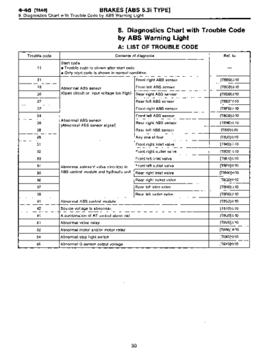
4-4a [TBAO1                               BRAKES [ABS 5.31 TYPE]
8. Diagnostics Chart with Trouble Code by ABS Warning Light


                                                    8 . Diagnostics Chart with Trouble Code
                                                    by ABS Warning Light
                                                    A: LIST OF TROUBLE CODE
    Trouble code                                   Contents of diagnosis                     Ref. to

                    Start code
         11         e Trouble code is shown after start code .                                 -
                    * Only start code is shown in normal condition .

        21                                                       Front right ABS sensor    [T8B0]*10

        23          Abnormal ABS sensor                          Front left ABS sensor     [T8C0]*10

        25          (Open circuit or input voltage too high)     Rear right ABS sensor     [T8D0]*10

        27                                                       Rear left ABS sensor      [T8E0]x10

        22                                                      Front right ABS sensor     [T8F0]*10

        24                                                      Front left ABS sensor      [T8G0]dr10
                    Abnormal ABS sensor
        26                                                      Rear right ABS sensor      [T8H0]*10
                    (Abnormal ABS sensor signal)
        28                                                      Rear left ABS sensor       [T810]*10

        29                                                      Any one of four            [T8J0]*10

        31                                                      Front right inlet valve    [T8K0]*10

        32                                                      Front right outlet valve   [7800]*10

        33                                                      Front left inlet valve     [TSLO]*10

        34         Abnormal solenoid valve circuit(s) in        Front left outlet valve    [T8PO]*10

        35         ABS control module and hydraulic unit        Rear right inlet valve     [T8M0]*10

        36                                                      Rear right outlet valve    [T8QOj*10

        37                                                      Rear left inlet valve      [T8N0]x10

        38                                                      Rear left outlet valve     [T8R0]*10

        41         Abnormal ABS control module                                             [T8SO1*10

        42         Source voltage is abnormal .                                            [7870]*10

        44         A combination of AT control abnormal                                    [T8U0]t`r10

        51         Abnormal valve relay                                                    [T8V0]*10

        52         Abnormal motor and/or motor relay                                       [T8W0]*10

        54         Abnormal stop light switch                                              (78X0]*10

        56         Abnormal G sensor output voltage                                        [T8Y0)*10


                                                               30
4-4d [rsBO]                              BRAKES [ABS 5.31 TYPE]
8. Diagnostics Chart with Trouble Code by ABS Warning Light


                                                 B: TROUBLE CODE 21 (FRONT RH)
                                                 C: TROUBLE CODE 23 (FRONT LH)
                                                 D : TROUBLE CODE 25 (REAR RH)
                                                 E : TROUBLE CODE 27 (REAR LH)
                                                 - ABNORMAL ABS SENSOR (OPEN CIRCUIT
                                                 OR INPUT VOLTAGE TOO HIGH) -
                                                 DIAGNOSIS :
                                                 " Faulty ABS sensor (Broken wire, input voltage too high)
                                                   Faulty harness connector
                                                 TROUBLE SYMPTOM:
                                                 * ABS does not operate.

                                                 WIRING DIAGRAM:

                     F49


                                                                                                 Front ABS
                                                                                                 sensor LH


                                                                                                 Front ABS
                                                                                                 sensor RH
       ABS
       control
       module
       and                                                                                                   Rear ABS
       hydraulic                                                                                             sensor LH
       control
       unit
                                                                                                             RearABS
                                                                                                             sensor RH


                                                                            r----------------
                                                                            I OUTBACK with step roof model               I

                                                                            I            Q                               I
                                                                                                         RearABS
                                                                                       -C~l              sensor LH
                                                                           I                                             I
                                                                                                         RearABS         j
                                                                                     ~--m                sensor RH

                                                                           I             Q            I
                                                                                         ------------J


 OUTBACK
 with step
 roof model        B~5 O

  O P8             OO              Ft                      100                                   f{9
                                                                           1       345678911112131415
                               1         3   1                    10      11 16 117 1181191202 122 4 26
                               4        78       70969                         7128129130131 1


                                                                                                                     B4M1238


                                                      32
                                           BRAKES [ABS 5 .31 TYPE]                                  [TSE2] 4-4d
                                                       8. Diagnostics Chart with Trouble Code by ABS Warning Light


Except OUTBACK model                                $E1        CHECK ABS SENSOR .
                                                    1) Turn ignition switch to OFF.
                      1 2                           2) Disconnect connector from ABS sensor.
                                                    3) Measure resistance of ABS sensor connector terminals .
                                                    Terminal
                                                    Front RH No. 1 - No. 2:
                  D                                 Front LH No. 1 - No. 2:
                      S2                            Rear RH No. 1 - No, 2:
                                         B4MOSO6E   Rear LH No. 1 - No. 2:
                                                     CHECK  : Is the resistance between 0.8 and 1 .2 kS2?
OUTBACK model
                                                     ,rES : Go to step 8E2.
                                  Rear
       Front
                                                      No : Replace ABS sensor.
        1 2                        2 1


                      D
                                         84M1036C


Except OUTBACK model                                8E2        I CHECK BATTERY SHORT OF ABS SENSOR .
                                                    1) Disconnect connector from ABSCM&H1U .
                            1 2                     2) Measure voltage between ABS sensor and chassis
                                                    ground .
                                                    Terminal
                                                    Front RH No. 1 (+) - Chassis ground ():
                                                    Front LH No. 1 (+) - Chassis ground ():
   f     L
               - Vq         1                       Rear RH No. 1 ( +) - Chassis ground ():
                                         B4MO807E   Rear LH No. 1 (+) - Chassis ground ():
                                                     CHECK : Is the voltage less than 1 V?
OUTBACK model
                                                    vES   : Go to step 8E3.
       Front                      Rear              No    : Replace ABS sensor.
                                  2 1


                  D
                  _v                     B4M1037C


                                                          33
4-4d    [T8E3]                         BRAKES [ABS 5.31        TYPE]
8. Diagnostics Chart with Trouble Code by ABS Warning Light


 Except OUTBACK model
                                                8E3        I CHECK BATTERY SHORT OF ABS SENSOR .
                                                1) Turn ignition switch to ON .
                      M112                      2) Measure voltage between ABS sensor and chassis
                                                ground .
                                                Terminal
                                                Front RH No. 1 (+) - Chassis ground ():

           L21   V                              Front LH No. 1 (+) - Chassis ground ():
                                                Rear RH No. 1 (+) - Chassis ground (-) :
                                     B4MOB07E   Rear LH No. 1 (+) - Chassis ground ():
                                                 CHECK : Is the voltage less than 1 V?
 OUTBACK model
                                                vES    : Go to step 8E4.
         Front                Rear              No     : Replace ABS sensor.
          DI
          1 2                 2 1


                     D
          -_
                     _v              B4M1037C


                                                8E4        CHECK                     ETWEEN
                                                           ABSCM&HU AND,ABS SENSOR .
                                                1) Turn ignition switch to OFF .
                                                2) Connect connector to ABS sensor.
                                                3) Measure resistance between ABSCM&H/U connector
                                                terminals.
                                                Connector & terminal
                                                Trouble code 21 / (F49) No. 11 - No. 12:
                                                Trouble code 23 / (F49) No. 9 - No. 10 :
                                                Trouble code 25 l (F49) No. 14 - No. 15:
                                                Trouble code 27 l (F49) No. 7 - No. 8:
                                                 CHECK  : Is the resistance between 0.8 and 1 .2 kSZ?
                                                 vES : Go to step 8E5 .
                                                  No : Repair harness/connector between ABSCM&H/U
                                                         and ABS sensor.


                                                      34
         BRAKES [ABS 5.31 TYPE]                                       [r8E71 4-4d
                         8. Diagnostics Chart with Trouble Code by ABS Warning Light


                                  fCHECK BATTERY SHORT OF HARNESS.
                     Measure voltage between ABSCM&H/U connector and
                     chassis ground .
                     Connector & terminal
                     Trouble code 21 I (F49) No. 11 (+) - Chassis ground

                     Trouble code 23 l (F49) No. 9 (+) - Chassis ground

                     Trouble code 25 l (F49) No. 14 (+) - Chassis ground

                     Trouble code 27 / (F49) No . 7 (+) - Chassis ground
                     (-):
                      CHECK : Is the voltage less than 1 V?
                      ves : Go to step 8E6.
                       No : Repair harness between ABSCM&H/U and ABS
                             sensor.


F49                  18E6         I CHECK BATTERY SHORT OF HARNESS.
                     1) Turn ignition switch to ON .
                     2) Measure voltage between ABSCM&H/U connector and
                     chassis ground .
                     Connector & terminal
                     Trouble code 21 / (F49) No. 11 (+) - Chassis ground

                     Trouble code 23 l (F49) No. 9 (+) - Chassis ground
      B4M 1240A 'I

                     Trouble code 25 l (F49) No. 14 (+) - Chassis ground

                     Trouble code 27 / (F49) No . 7 (+) - Chassis ground

                     CHECK    : Is the voltage less than 1 V?
                     ves     : Go to step 8E7.
                     No      : Repair harness between ABSCM&H/U and ABS
                               sensor.


                     8E7          CHECK INSTALLATION OF ABS SENSOR .
                     Tightening torque:
                     32 f 10 N~m (3.3 f 1 .0 kg-m, 24 f 7 ft-Ib)
                      CHECK  : Are the ABS sensor installation bolts tight-
                               ened securel y?
                     vES     : Go to step 8E8.
                     No      : Tighten ABS sensor installation bolts securely .


                             35
4-4d [TSES1                           BRAKES [ABS 5.31 TYPE]
8. Diagnostics Chart with Trouble Code by ABS Warning Light


                                                 8E8         CHECK INSTALLATION OF TONE WHEEL.
                                                           I
                                                 Tightening torque:
                                                 13 f 3 N~m (1.3 f 0.3 kg-m, 9 f 2.2 ft-Ib)
                                                  CHECK  : Are the tone wheel installation bolts tight-
                                                             ened securely?
                                                  ,rES : Go to step 8E9.
                                                   No : Tighten tone wheel installation bolts securely .


                                                 8E9          CHECK ABS SENSOR GAP.
                                                            I
                                                 Measure tone wheel-to-pole piece gap over entire perim-
                                                 eter of the wheel .
                                                  CHECK   ; Is the gap within the specifications shown in
                                                              the following table?

                                                                     Front wheel          Rear wheel
                 Sensor gap                      Specifications     0 .9 - 1 .4 mm        0 .7 - 1 .2 mm
                                     G4M0700 I                      (0.035 - 0 .055 in)   (0 .028 - 0 .047 in)


                                                  ves : Go to step 8E10 .
                              Rear
                                                   No : Adjust the gap .
                                                 NOTE :
                                                 Adjust the gap using spacers (Part No. 26755AA000) . If
                                                 spacers cannot correct the gap, replace worn sensor or
                                                 worn tone wheel.


                 Sensor gap
                                     G4M0701


                                                 8E10        CHECK HUB RUNOUT.
                                                 Measure hub runout.
                                                 CHECK  : Is the runouf less than 0.05 mm (0 .0020 in)?
                                                  vES : Go to step 8E11 .
                                                  No : Repair hub.


                                                        36
                                  BRAKES [ABS 5.3i TYPE]                                   [T8E13] 4-4d
                                              8. Diagnostics Chart with Trouble Code by ABS Warning Light


Except OUTBACK model                                    CHECK GROUND SHORT OF ABS SENSOR .
                                           1) Turn ignition switch to ON .
                   1 2                     2) Measure resistance between ABS sensor and chassis
                                           ground .
                                           Terminal
                                           Front RH No. 1 - Chassis ground:
        L     D                            Front LH No. 1 - Chassis ground:
              S2                           Rear RH No. 1 - Chassis ground:
                                B4M0818E   Rear LH No. 1 - Chassis ground:
                                            CHECK   : Is the resistance more than 1 MS2?
OUTBACK model
                                            ,rES : Go to step 8E12.
      Front              Rear                No : Replace ABS sensor and ABSCM&H/U .
       JT~
       1 2
              L 2        2 1


                                B4M1042C


                                                        CHECK GROUND SHORT OF HARNESS .
                                           1) Turn ignition switch to OFF .
                                           2) Connect connector to ABS sensor.
                                           3) Measure resistance between ABSCM&H/U connector
                                           terminal and chassis ground .
                                           Connector & terminal
                                           Trouble code 21 I (F49) No . 11 - Chassis ground:
                                           Trouble code 23 l (F49) No. 9 - Chassis ground:
                                           Trouble code 25 I (F49) No . 14 - Chassis ground:
                                           Trouble code 27 / (F49) No. 7 - Chassis ground:
                                            CHECK ; Is the resistance more than 1 MS2?
                                           ,rES    : Go to step 8E13.
                                           No      : Repair harness between ABSCM&H/U and ABS
                                                     sensor .
                                                     Replace ABSCM&H/U .


                                                        (CHECK POOR CONTACT IN CONNECTORS .
                                           CHECK    : Is there poor contact in connectors between
                                                      ABSCM&HIU and ABS sensor? < Ref. to
                                                      FOREWORD [T3C1] .*10 >
                                           vES     : Repair connector.
                                           No      : Go to step 8E14 .


                                                   37
4-4d [T8E14]                          BRAKES [ABS 5 .31 TYPE]
8. Diagnostics Chart with Trouble Code by ABS Warning Light


                                                  -
                                              f 8E14     CHECK ABSCM&H/U.
                                              I
                                                1) Connect all connectors .
                                              2) Erase the memory.
                                              3) Perform inspection mode .
                                              4) Read out the trouble code .
                                                 CHECK : Is the same trouble code as in the current
                                                         diagnosis still being output?
                                                 ves : Replace ABSCM&H/U.
                                                  No : Go to step 8E15 .


                                              I8E1 5       CHECK ANY .THER TROUBLE CODES
                                                          IAPPEARANCE
                                                          Are other trouble codes being output?
                                                         Proceed with the diagnosis corresponding to the
                                                         trouble code.
                                               No      : A temporary poor contact.
                                              NOTE :
                                              Check harness and connectors between ABSCM&H/U
                                              and ABS sensor .


                                                    38
4-4d [TSFO]                             BRAKES [ABS 5.31 TYPE]
8. Diagnostics Chart with Trouble Code by ABS Warning Light


                                                   F: TROUBLE CODE 22 (FRONT RH)
                                                   G : TROUBLE CODE 24 (FRONT LH)
                                                   H : TROUBLE CODE 26 (REAR RH)
                                                   I: TROUBLE CODE 28 (REAR LH)
                                                   - ABNORMAL ABS SENSOR (ABNORMAL
                                                   ABS SENSOR SIGNAL) -
                                                   DIAGNOSIS :
                                                   " Faulty ABS sensor signal (noise, irregular signal, etc .)
                                                     Faulty harness/connector
                                                   TROUBLE SYMPTOM:
                                                   9 ABS does not operate.

                                                   WIRING DIAGRAM :

                     f49

                                                                            _-^     B15
                                            ~ B~~                   _____===_-r    m--~~ Front ABS
                                                                                      ~ sensor LH

                                  ----                               -----------
                                  ---                                                        Front ABS
                                                                    -
                                                                    -----------    [Z1-1   ~ sensor RH
      ABS                         Twisted                                               ~-
      control                     wire    F1        Pt                             O     O
      module
      and                                                                                                        Rear ABS
      hydraulic                                                                                                  sensor LH
      control
      unit                        ~ :M
                                   :                            Twisted wire
                                                                                                                RearABS
                                                                                                                sensor RH


                                                                                     I OUTBACK with step roof model              I

                                                                                     I        ~                                  I
                                                                                                                RearABS


◦ Jabse Service Manual Search 2026 ◦ Jabse PravopisonTap.bg ◦ Other service manual resources online : FixyaeServiceinfo