Service Manuals, User Guides, Schematic Diagrams or docs for : . Car Manuals Subaru Legacy 1995-1999 Approved Subaru Legacy 1997 1997 Service Manual BODY SECTION SUPPLEMENTAL RESTRAINT SYSTEM (ELECTRIC SENSOR TYPE) MSA5TCD97L3853
<< Back | HomeMost service manuals and schematics are PDF files, so You will need Adobre Acrobat Reader to view : Acrobat Download Some of the files are DjVu format. Readers and resources available here : DjVu Resources
For the compressed files, most common are zip and rar. Please, extract files with Your favorite compression software ( WinZip, WinRAR ... ) before viewing. If a document has multiple parts, You should download all, before extracting.
Good luck. Repair on Your own risk. Make sure You know what You are doing.
Image preview - the first page of the document
>> Download MSA5TCD97L3853 documenatation <<
Text preview - extract from the document
  SERVICE PROCEDURE                                               5-5b
                                       3. Airbag Module - 4. Main Harness


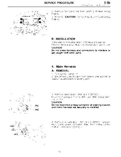
          2) Remove four bolts and then carefully remove airbag
          module.
          3) Refer to "CAUTION" for handling of a removed airbag
          module.


B5M0098


          B: INSTALLATION
          Installation is in reverse order of removal procedures.
          Observe the following: Make sure that ignition switch is off.
          CAUTION:
          Do not allow harness and connectors to interfere or
          get caught with other parts.


          4. Main Harness
          A: REMOVAL
          1) Turn ignition switch off.
          2) Disconnect ground cable from battery and wait for at
          least 20 seconds before starting work.


          3) Remove lower cover.
          Disconnect airbag connector (AB3) and (AB8) below steer-
          ing column.
          CAUTION:
          Do not reconnect airbag connector at steering column
          until main harness are securely re-installed.


G5M0312


          4) Remove console box.  Discon-
          nect 12-pin yellow connector (AB6) from airbag control
          module.


G5M0313


                13
5-5b                                     SERVICE PROCEDURE
4. Main Harness - 5. Airbag Control Module


                                                 5) Disconnect body harness connector (B53) from connec-
                                                 tor (AB1).
                                                 NOTE:
                                                 The following procedures for removal are for "LHD model".
                                                 The procedures for "RHD model" are symmetrically oppo-
                                                 site.


                                      B5M0103A


                                                 6) Remove front side sill cover and then disconnect airbag
                                                 connector (AB9) and (AB10).


                                      B5M0029A


                                                 7) Roll up floor mat and side sill lower cover of both side
                                                 and then remove main harness.


                                       B5M0104


                                                 B: INSTALLATION
                                                 Installation is in reverse order of removal procedures.


                                                 5. Airbag Control Module
                                                 CAUTION:
◦ Jabse Service Manual Search 2026 ◦ Jabse Pravopis ◦ onTap.bg ◦ Other service manual resources online : Fixya ◦ eServiceinfo