Service Manuals, User Guides, Schematic Diagrams or docs for : . Car Manuals Subaru Legacy 1995-1999 Approved Subaru Legacy 1997 1997 Service Manual DIAGNOSTICS SECTION FOREWORD MSA5TCD97L30673
<< Back | HomeMost service manuals and schematics are PDF files, so You will need Adobre Acrobat Reader to view : Acrobat Download Some of the files are DjVu format. Readers and resources available here : DjVu Resources
For the compressed files, most common are zip and rar. Please, extract files with Your favorite compression software ( WinZip, WinRAR ... ) before viewing. If a document has multiple parts, You should download all, before extracting.
Good luck. Repair on Your own risk. Make sure You know what You are doing.
Image preview - the first page of the document
>> Download MSA5TCD97L30673 documenatation <<
Text preview - extract from the document
          FOREWORD                                   [T4A2] FOREWORD
                     4. Diagnosis and Checking Procedure Using Instruments


          4. Diagnosis and Checking Procedure
          Using Instruments
          A: USING A CIRCUIT TESTER
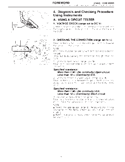
          1. VOLTAGE CHECK (range set to DC V)
          Connect the positive probe to the terminal to be tested, and
          the negative probe to body ground. (or the ground terminal of
          the ECM)
B0M0020


          2. CHECKING THE CONNECTION (range set to )
          Measure the resistance and check for open or shorted wire in
          the harness or the connector.
          NOTE:
          This check must be carried out with both connectors discon-
          nected.
          (This avoids by-passing the connection through other cir-
          cuits.)
          1) Check for open circuit. (range:  x 1K)
B0M0021   Measure the resistance between the respective pins in both
          connectors.
          Specified resistance:
             More than 1 M (No continuity) Open circuit
             Less than 10  (Continuity) O.K.
          2) Check for correct insulation value. (range:  x 1K)
          Measure the resistance between the pins in both connectors,
          as well as between the suspected pin and the body. (body
          short)
          Specified resistance:
             More than 1 M (No continuity) O.K.
             Less than 10  (Continuity) Short circuit
          3) Resistance measurement (range set to )
          Measuring the internal resistance of sensors, solenoid valves
          etc. to check the operating condition of components.
          NOTE:
◦ Jabse Service Manual Search 2026 ◦ Jabse Pravopis ◦ onTap.bg ◦ Other service manual resources online : Fixya ◦ eServiceinfo