Service Manuals, User Guides, Schematic Diagrams or docs for : . Car Manuals Subaru Legacy 1995-1999 Approved Subaru Legacy 1997 1997 Service Manual ENGINE SECTION ENGINE (SOHC) MSA5TCD97L3457
<< Back | HomeMost service manuals and schematics are PDF files, so You will need Adobre Acrobat Reader to view : Acrobat Download Some of the files are DjVu format. Readers and resources available here : DjVu Resources
For the compressed files, most common are zip and rar. Please, extract files with Your favorite compression software ( WinZip, WinRAR ... ) before viewing. If a document has multiple parts, You should download all, before extracting.
Good luck. Repair on Your own risk. Make sure You know what You are doing.
Image preview - the first page of the document
>> Download MSA5TCD97L3457 documenatation <<
Text preview - extract from the document
   SERVICE PROCEDURE                                             2-3
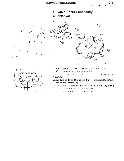
                                              4. Valve Rocker Assembly


           4. Valve Rocker Assembly
           A: REMOVAL


                                                             B2M1206A


           1) Disconnect PCV hose and remove rocker cover.
           2) Removal of valve rocker assembly
              (1) Remove bolts k through k in numerical sequence.
                                 1           4
           CAUTION:
           Leave two or three threads of bolt k engaged to retain
                                                1
           valve rocker assembly.
              (2) Equally loosen bolts k through k all the way, being
                                        5         8
              careful that knock pin is not gouged.
B2M1207A      (3) Remove valve rocker assembly.


                 27
2-3                        SERVICE PROCEDURE
4. Valve Rocker Assembly


                               B: DISASSEMBLY


                                                                              B2M1264A

                               1) Remove bolts which secure rocker shaft.
                               2) Extract rocker shaft. Remove valve rocker arms,
                               springs and shaft supports from rocker shaft.
                               CAUTION:
                               Arrange all removed parts in order so that they can be
                               installed in their original positions.


                               3) Loosen rocker nut, and then remove rocker screw and
                               nut from rocker arm.
                               CAUTION:
                               Do not remove rocker screw and nut unless necessary.


                                    28
  SERVICE PROCEDURE                                                2-3
                                                4. Valve Rocker Assembly


          C: INSPECTION
          1. HYDRAULIC LASH ADJUSTER
          1) Bleed air from hydraulic lash adjuster as described
          below:
             (1) While dipping hydraulic lash adjuster in engine oil,
             as shown in Figure, push check ball in using a 2 mm
             (0.08 in) diameter round bar.
             (2) With check ball pushed in, manually move plunger
             up and down at one second intervals until air bubbles
G2M0131
             disappear.
             (3) After air bubbles disappear, remove round bar and
             quickly push plunger in to ensure it is locked. If plunger
             does not lock properly, replace hydraulic lash adjuster.
          CAUTION:
          Leave hydraulic lash adjuster (after air is bled) in
          engine oil until it is ready for installation.


          2) Replace hydraulic lash adjuster with a new one if valve
          contact surface is scratched.


                29
2-3                          SERVICE PROCEDURE
4. Valve Rocker Assembly


                                     2. VALVE ROCKER ARM
                                     1) Measure inside diameter of valve rocker arm and out-
                                     side diameter of valve rocker shaft, and determine the dif-
                                     ference between the two (= oil clearance).
                                     Clearance between arm and shaft:
                                          Standard
                                              0.020 -- 0.054 mm (0.0008 -- 0.0021 in)
                                          Limit
                                              0.10 mm (0.0039 in)
                           B2M0072
                                     If oil clearance exceeds specifications, replace valve
                                     rocker arm or shaft.
                                     NOTE:
                                     Replace valve rocker arm or shaft, whichever shows
                                     greater amount of wear.
                                     Rocker arm inside diameter:
                                          22.020 -- 22.041 mm (0.8669 -- 0.8678 in)
                                     Rocker shaft diameter:
                                          21.987 -- 22.000 mm (0.8656 -- 0.8661 in)
                                     2) Measure inside diameter of rocker shaft support and
                           B2M0073   outside diameter of valve rocker shaft, and determine the
                                     difference between the two (= oil clearance).
                                     Clearance between support and shaft:
                                          Standard
                                              0.005 -- 0.039 mm (0.0002 -- 0.0015 in)
                                          Limit
                                              0.05 mm (0.0020 in)
                                     If oil clearance exceeds specifications, replace rocker shaft
                                     support or shaft.
                                     NOTE:
                                     Replace rocker shaft support or shaft, whichever shows
                                     greater amount of wear.
                                     Rocker shaft support inside diameter:
                                          22.005 -- 22.026 mm (0.8663 -- 0.8672 in)
                                     Rocker shaft diameter:
                                          21.987 -- 22.000 mm (0.8656 -- 0.8661 in)
                                     3) If cam or valve contact surface of valve rocker arm is
                                     worn or dented excessively, replace valve rocker arm.
                                     4) Check that valve rocker arm roller rotates smoothly. If
                                     not, replace valve rocker arm.


                                     3. VALVE ROCKER SHAFT
                                     Visually check oil relief valve of shaft end for any of the
                                     following abnormalities.
◦ Jabse Service Manual Search 2026 ◦ Jabse Pravopis ◦ onTap.bg ◦ Other service manual resources online : Fixya ◦ eServiceinfo