Service Manuals, User Guides, Schematic Diagrams or docs for : . Car Manuals Subaru Legacy 1995-1999 Approved Subaru Legacy 1997 1997 Service Manual ELECTRICAL SECTION BODY ELECTRICAL SYSTEM MSA5TCD97L3890
<< Back | HomeMost service manuals and schematics are PDF files, so You will need Adobre Acrobat Reader to view : Acrobat Download Some of the files are DjVu format. Readers and resources available here : DjVu Resources
For the compressed files, most common are zip and rar. Please, extract files with Your favorite compression software ( WinZip, WinRAR ... ) before viewing. If a document has multiple parts, You should download all, before extracting.
Good luck. Repair on Your own risk. Make sure You know what You are doing.
Image preview - the first page of the document
>> Download MSA5TCD97L3890 documenatation <<
Text preview - extract from the document
6-2                                      SERVICE PROCEDURE
19. Sunroof - 20. Radio, Speaker and Antenna


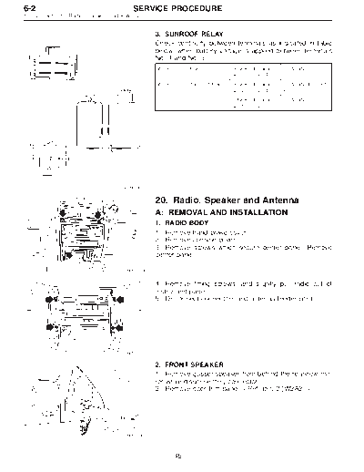
                                                3. SUNROOF RELAY
                                                Check continuity between terminals as indicated in table
                                                below, when battery voltage is applied between terminals
                                                No. 1 and No. 3.
                                                When current flows.           Between terminals   Continuity exists.
                                                                              No. 2 and No. 4
                                                When current does not flow.   Between terminals   Continuity does not
                                                                              No. 2 and No. 4     exist.
                                                                              Between terminals   Continuity exists.
                                                                              No. 1 and No. 3


                                     B6M0144A


                                                20. Radio, Speaker and Antenna
                                                A: REMOVAL AND INSTALLATION
                                                1. RADIO BODY
                                                1) Remove hand brake cover.
                                                2) Remove console cover.
                                                3) Remove screws which secure center panel. Remove
                                                center panel.

                                      B6M0354


                                                4) Remove fitting screws, and slightly pull radio out of
                                                instrument panel.
                                                5) Disconnect connectors and antenna feeder cord.


                                      B6M0355

                                                2. FRONT SPEAKER
                                                1) Remove gusset speaker from behind the rearview mir-
                                                ror while disconnecting connector.
                                                2) Remove door trim panel.


                                      B6M0146


                                                       46
   SERVICE PROCEDURE                                               6-2
                                          20. Radio, Speaker and Antenna


           3) Disconnect connector from speaker.
           4) Remove screws which secure the speaker.
           5) Remove door mount speaker.


 B6M0162


           3. REAR SPEAKER (SEDAN)
           1) Remove rear seat cushion and rear backrest.
           2) Remove left and right rear quarter trim panels.
           3) Remove rear shelf trim panel.
           4) Remove screws which secure speaker.
           5) Remove speaker while disconnecting connector from
           speaker.


           4.   REAR SPEAKER (WAGON)
           1)   Remove door trim panel.
           2)   Disconnect connector from speaker.
           3)   Remove screws which secure the speaker.
           4)   Remove speaker.


           5. POWER ANTENNA
           1) Remove left side trunk trim (SEDAN), or left side rear
           lower quarter trim (WAGON).
           2) Remove special nut (SEDAN).
           3) Remove bolt which secures power antenna.
           4) Remove power antenna while disconnecting connector
           and water drain hose.


B6M0147A


           B: INSPECTION
           1. POWER ANTENNA
           1) Connect battery positive (+) terminal to terminal No. 3
           and connect terminal No. 1 (SEDAN) or No. 6 (WAGON)
           to ground. Ensure that antenna rod extends properly when
           battery positive (+) terminal is connected to terminal No. 2
           (SEDAN) or No. 4 (WAGON).
           2) Ensure that antenna rod retracts properly when battery
           positive (+) terminal is disconnected from terminal No. 2
B6M0149A
           (SEDAN) or No. 4 (WAGON).

                  47
◦ Jabse Service Manual Search 2026 ◦ Jabse Pravopis ◦ onTap.bg ◦ Other service manual resources online : Fixya ◦ eServiceinfo