Service Manuals, User Guides, Schematic Diagrams or docs for : . Car Manuals Subaru Legacy 1995-1999 Approved Subaru Legacy 1997 1997 Service Manual MECHANICAL COMPONENTS SECTION BRAKES MSA5TCD97L3704
<< Back | HomeMost service manuals and schematics are PDF files, so You will need Adobre Acrobat Reader to view : Acrobat Download Some of the files are DjVu format. Readers and resources available here : DjVu Resources
For the compressed files, most common are zip and rar. Please, extract files with Your favorite compression software ( WinZip, WinRAR ... ) before viewing. If a document has multiple parts, You should download all, before extracting.
Good luck. Repair on Your own risk. Make sure You know what You are doing.
Image preview - the first page of the document
>> Download MSA5TCD97L3704 documenatation <<
Text preview - extract from the document
4-4                                     SERVICE PROCEDURE
16. ABS Control Module (ABS 5.3 Type) - 17. G Sensor for ABS System (ABS 5.3 Type)


                                                B: INSPECTION
                                                Check that connector is connected correctly and that con-
                                                nector terminal sliding resistance is correct.
                                                C: INSTALLATION
                                                To install, reverse the removal procedure.


                                                17. G Sensor for ABS System (ABS 5.3
                                                Type)
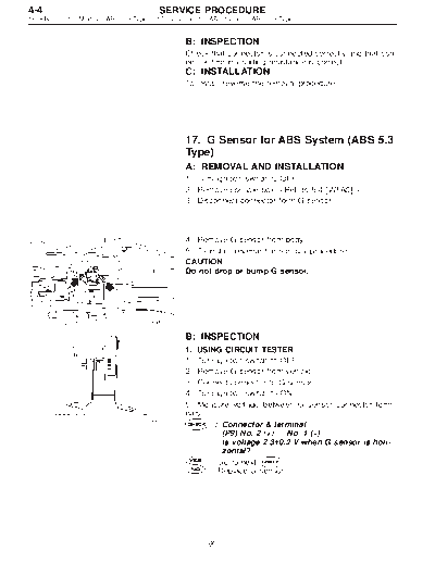
                                                A: REMOVAL AND INSTALLATION
                                                1) Turn ignition switch to OFF.
                                                2) Remove console box.
                                                3) Disconnect connector form G sensor.


                                                4) Remove G sensor from body.
                                                5) To install, reverse the removal procedure.
                                                CAUTION:
                                                Do not drop or bump G sensor.


                                      B4M1011


                                                B: INSPECTION
                                                1. USING CIRCUIT TESTER
                                                1) Turn ignition switch to OFF.
                                                2) Remove G sensor from vehicle.
                                                3) Connect connector to G sensor.
                                                4) Turn ignition switch to ON.
                                                5) Measure voltage between G sensor connector termi-
                                                nals.
                                     B4M0915
                                                       : Connector & terminal
                                                          (P9) No. 2 (+) -- No. 1 (-)
                                                          Is voltage 2.3
◦ Jabse Service Manual Search 2026 ◦ Jabse Pravopis ◦ onTap.bg ◦ Other service manual resources online : Fixya ◦ eServiceinfo