Service Manuals, User Guides, Schematic Diagrams or docs for : . Car Manuals Subaru Legacy 1995-1999 Approved Subaru Legacy 1997 1997 Service Manual MECHANICAL COMPONENTS SECTION BRAKES MSA5TCD97L3703
<< Back | HomeMost service manuals and schematics are PDF files, so You will need Adobre Acrobat Reader to view : Acrobat Download Some of the files are DjVu format. Readers and resources available here : DjVu Resources
For the compressed files, most common are zip and rar. Please, extract files with Your favorite compression software ( WinZip, WinRAR ... ) before viewing. If a document has multiple parts, You should download all, before extracting.
Good luck. Repair on Your own risk. Make sure You know what You are doing.
Image preview - the first page of the document
>> Download MSA5TCD97L3703 documenatation <<
Text preview - extract from the document
4-4                                      SERVICE PROCEDURE
15. Hydraulic Unit for ABS System (ABS 5.3 Type) - 16. ABS Control Module (ABS 5.3 Type)


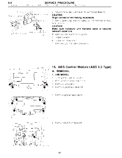
                                                 2) Secure relay box connector to connector bracket.
                                                 CAUTION:
                                                 Align connector wit mating receptacle.
                                                 3) Using cable clip, secure hydraulic unit harness to relay
                                                 box harness.
                                                 CAUTION:
                                                 Make sure hydraulic unit harness band is secured
                                                 beneath cable clip.
                                     B4M1031A    4) Connect connector to relay box.
                                                 5) Install canister.
                                                 6) Install air intake duct.
                                                 7) Connect ground cable to battery.


                                                 16. ABS Control Module (ABS 5.3 Type)
                                                 A: REMOVAL
                                                 1.   LHD MODEL
                                                 1)   Turn ignition switch to OFF.
                                                 2)   Remove front pillar lower trim.
                                                 3)   Remove glove box.
                                                 4)   Remove glove box bracket.
                                      B4M1002


                                                 5) Remove pocket back panel.


                                      B4M1003


                                                 6) Remove bolt from bracket.


                                      B4M1004


                                                         88
   SERVICE PROCEDURE                                               4-4
                                   16. ABS Control Module (ABS 5.3 Type)


           7) Remove bolt cover and bolt.


 B4M1005


           8) Remove ABSCM upper mounting bolt.


 B4M1006


           9) Pull the lower part of the instrument panel rearward 5
           cm (1.97 in).
           CAUTION:
           When pulled more than 6 cm (2.4 in), the instrument
           panel may be deformed.
           NOTE:
           At this time, instrument panel securing clips can be
           removed.
B4M1045A


           10) Remove two ABSCM lower mounting bolts from the
           lower part of the instrument panel.


 B4M1008


           11) While holding the lower part of instrument panel rear-
           ward 5 cm (1.97 in) remove the ABSCM.
           CAUTION:
           When pulled more than 6 cm (2.4 in), the instrument
           panel may be deformed.
           12) Disconnect connector from ABSCM.
           CAUTION:
           Do not drop or bump ABSCM.
B4M1009A


                 89
4-4                                     SERVICE PROCEDURE
16. ABS Control Module (ABS 5.3 Type) - 17. G Sensor for ABS System (ABS 5.3 Type)


                                                B: INSPECTION
                                                Check that connector is connected correctly and that con-
                                                nector terminal sliding resistance is correct.
                                                C: INSTALLATION
                                                To install, reverse the removal procedure.


                                                17. G Sensor for ABS System (ABS 5.3
                                                Type)
                                                A: REMOVAL AND INSTALLATION
                                                1) Turn ignition switch to OFF.
                                                2) Remove console box.
                                                3) Disconnect connector form G sensor.


                                                4) Remove G sensor from body.
                                                5) To install, reverse the removal procedure.
                                                CAUTION:
                                                Do not drop or bump G sensor.


                                      B4M1011


                                                B: INSPECTION
                                                1. USING CIRCUIT TESTER
                                                1) Turn ignition switch to OFF.
                                                2) Remove G sensor from vehicle.
                                                3) Connect connector to G sensor.
                                                4) Turn ignition switch to ON.
                                                5) Measure voltage between G sensor connector termi-
                                                nals.
                                     B4M0915
                                                       : Connector & terminal
                                                          (P9) No. 2 (+) -- No. 1 (-)
                                                          Is voltage 2.3
◦ Jabse Service Manual Search 2026 ◦ Jabse Pravopis ◦ onTap.bg ◦ Other service manual resources online : Fixya ◦ eServiceinfo