Service Manuals, User Guides, Schematic Diagrams or docs for : . Car Manuals Subaru Legacy 1995-1999 Approved Subaru Legacy 1997 1997 Service Manual TRANSMISSION AND DIFFERENTIAL SECTION MANUAL TRANSMISSION AND DIFFERENTIAL MSA5TCD97L3578
<< Back | HomeMost service manuals and schematics are PDF files, so You will need Adobre Acrobat Reader to view : Acrobat Download Some of the files are DjVu format. Readers and resources available here : DjVu Resources
For the compressed files, most common are zip and rar. Please, extract files with Your favorite compression software ( WinZip, WinRAR ... ) before viewing. If a document has multiple parts, You should download all, before extracting.
Good luck. Repair on Your own risk. Make sure You know what You are doing.
Image preview - the first page of the document
>> Download MSA5TCD97L3578 documenatation <<
Text preview - extract from the document
   SERVICE PROCEDURE                                               3-1
                                    6. Drive Pinion Assembly (FWD Model)


           6) Recheck that starting torque is within specified range,
           then clinch lock nut at four positions.


           6. Drive Pinion Assembly (FWD Model)
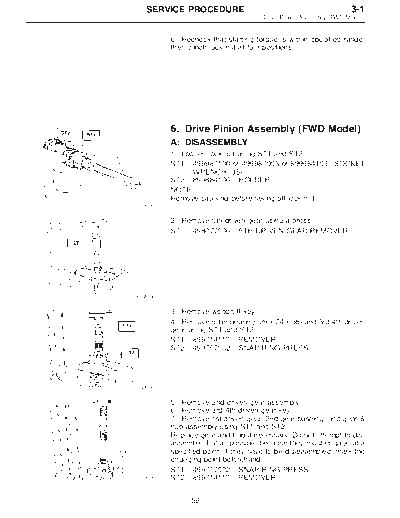
           A: DISASSEMBLY
           1) Loosen lock nut using ST1 and ST2.
           ST1 499987100 or 499987003 or 899984103 SOCKET
                 WRENCH (35)
           ST2 899884100 HOLDER
           NOTE:
           Remove caulking before taking off lock nut.
G3M0628


           2) Remove 5th driven gear using a press.
           ST   498077000 5TH DRIVEN GEAR REMOVER


B3M0341A


           3) Remove woodruff key.
           4) Remove roller bearing (29 x 74 x 38) and 3rd-4th driven
           gear using ST1 and ST2.
           ST1 899714110 REMOVER
           ST2 499757002 SNAP RING PRESS


G3M0610


           5) Remove 2nd driven gear assembly.
           6) Remove 3rd-4th driven gear key.
           7) Remove 1st driven gear, 2nd gear bushing, and gear &
           hub assembly using ST1 and ST2.
           Replace gear and hub if necessary. Do not attempt to dis-
           assemble if at all possible because they must engage at a
           specified point. If they have to be disassembled, mark the
           engaging point beforehand.
           ST1 499757002 SNAP RING PRESS
 G3M0611   ST2 899714110 REMOVER


                 59
3-1                                       SERVICE PROCEDURE
6. Drive Pinion Assembly (FWD Model)


                                                  8) Remove 1st gear bushing, 1st driven gear thrust plate,
                                                  and roller bearing (41 x 71 x 23) using ST and press.
                                                  ST     498517000 REPLACER
                                                  CAUTION:
                                                  Replace roller bearing (41 x 71 x 23) with a new one if
                                                  this disassembly is performed.


                                       G3M0632


                                                  B: ASSEMBLY
                                                  1) Assemble gear and hub assembly.
                                                  k : 1st gear side
                                                   A
                                                  k : 2nd gear side
                                                   B
                                                  k : Flush surface
                                                   C
                                                  k : Stepped surface
                                                   D
                                                  NOTE:
◦ Jabse Service Manual Search 2026 ◦ Jabse Pravopis ◦ onTap.bg ◦ Other service manual resources online : Fixya ◦ eServiceinfo