Service Manuals, User Guides, Schematic Diagrams or docs for : . Car Manuals Subaru Legacy 1995-1999 Approved Subaru Legacy 1997 1997 Service Manual TRANSMISSION AND DIFFERENTIAL SECTION MANUAL TRANSMISSION AND DIFFERENTIAL MSA5TCD97L3581
<< Back | HomeMost service manuals and schematics are PDF files, so You will need Adobre Acrobat Reader to view : Acrobat Download Some of the files are DjVu format. Readers and resources available here : DjVu Resources
For the compressed files, most common are zip and rar. Please, extract files with Your favorite compression software ( WinZip, WinRAR ... ) before viewing. If a document has multiple parts, You should download all, before extracting.
Good luck. Repair on Your own risk. Make sure You know what You are doing.
Image preview - the first page of the document
>> Download MSA5TCD97L3581 documenatation <<
Text preview - extract from the document
3-1                       SERVICE PROCEDURE
9. Front Differential


                                  9. Front Differential
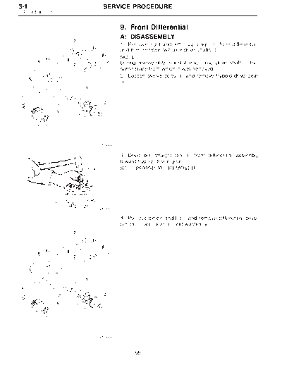
                                  A: DISASSEMBLY
                                  1) Remove right and left snap rings k from differential,
                                                                        1
                                  and then remove two axle drive shafts k .
                                                                         2
                                  NOTE:
                                  During reassembly, reinstall each axle drive shaft in the
                                  same place from which it was removed.
                                  2) Loosen twelve bolts k and remove hypoid drive gear
                                                          3
                                  k.
                                   4


                        G3M0666


                                  3) Drive out straight pin k from differential assembly
                                                             5
                                  toward hypoid driven gear.
                                  ST    899904100 REMOVER


                        G3M0667


                                  4) Pull out pinion shaft k , and remove differential bevel
                                                           6
                                  pinion k and gear k and washer k .
                                         7            8              9


                        G3M0666


                                        68
   SERVICE PROCEDURE                                                       3-1
                                                            9. Front Differential


           5) Remove roller bearing using ST.
           ST   399527700 PULLER SET


G3M0668


           B: ASSEMBLY
           1) Install bevel gear and bevel pinion together with
           washers, and insert pinion shaft k .
                                            1
           NOTE:
           Face the chamfered side of washer toward gear.


B3M0099A


           2) Measure backlash between bevel gear and pinion. If it
           is not within specifications, install a suitable washer to
           adjust it.
           Standard backlash:
               0.13 -- 0.18 mm (0.0051 -- 0.0071 in)
           ST1 498247001 MAGNET BASE
           ST2 498247100 DIAL GAUGE
           NOTE:
           Be sure the pinion gear tooth contacts adjacent gear teeth
G3M0670
           during measurement.
                                  Washer (38.1 x 50 x t)
                       Part No.                      Thickness mm (in)
                      803038021              0.925 -- 0.950 (0.0364 -- 0.0374)
                      803038022              0.975 -- 1.000 (0.0384 -- 0.0394)
                      803038023              1.025 -- 1.050 (0.0404 -- 0.0413)


                 69
3-1                       SERVICE PROCEDURE
9. Front Differential


                                  3) Align pinion shaft and differential case at their holes,
                                  and drive straight pin k into holes from the hypoid driven
                                                          5
                                  gear side, using ST.
                                  ST     899904100 REMOVER
                                  NOTE:
                                  Lock straight pin after installing.


                        G3M0666


                                  4) Install roller bearing (40 x 80 x 19.75) to differential
                                  case.
                                  NOTE:
                                  Be careful because roller bearing outer races are used as
                                  a set.
                                  ST1 499277100 BUSH 1-2 INSTALLER
                                  ST2 398497701 ADAPTER

                        G3M0671


                                  5) Install hypoid driven gear k to differential case k using
                                                                4                      10
                                  twelve bolts k .
                                                3
                                  Tightening torque:
                                     62
◦ Jabse Service Manual Search 2026 ◦ Jabse Pravopis ◦ onTap.bg ◦ Other service manual resources online : Fixya ◦ eServiceinfo