Service Manuals, User Guides, Schematic Diagrams or docs for : . Car Manuals Subaru Legacy 1995-1999 Approved Subaru Legacy 1998 1998 Service Manual ENGINE SECTION FUEL INJECTION SYSTEM MSA5TCD98L20915
<< Back | HomeMost service manuals and schematics are PDF files, so You will need Adobre Acrobat Reader to view : Acrobat Download Some of the files are DjVu format. Readers and resources available here : DjVu Resources
For the compressed files, most common are zip and rar. Please, extract files with Your favorite compression software ( WinZip, WinRAR ... ) before viewing. If a document has multiple parts, You should download all, before extracting.
Good luck. Repair on Your own risk. Make sure You know what You are doing.
Image preview - the first page of the document
>> Download MSA5TCD98L20915 documenatation <<
Text preview - extract from the document
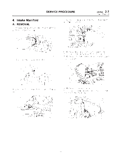
SERVICE PROCEDURE [W4A0] 2-7
4. Intake Manifold
4. Intake Manifold 5) Loosen clamp which connects air intake duct to
air intake chamber.
A: REMOVAL
1) Release fuel pressure.
2) Remove fuel filler cap.
B2M1226A
6) Remove two clips of air cleaner upper cover.
7) Disconnect blow-by hose from air intake duct.
B2M1746 8) Remove air intake duct and air cleaner upper
3) Disconnect battery ground cable. cover as a unit.
B2M1227
B2M1723
4) Disconnect connector from mass air flow sen- 9) Remove air cleaner element.
sor. 10) Loosen clamp which connects air intake
chamber to throttle body.
B2M1225A
B2M1218
11
2-7 [W4A0] SERVICE PROCEDURE
4. Intake Manifold
11) Disconnect air hoses, and remove air intake (3) Remove bolts which secure power steering
chamber. pipe brackets to intake manifold.
12) Disconnect accelerator cable (A). NOTE:
13) Disconnect cruise control cable (B). (With Do not disconnect power steering hose.
cruise control model)
S2M0085
B2M1190A
(4) Remove bolts which install power steering
14) Disconnect vacuum hoses from pressure pump to bracket.
sources switching solenoid valve.
15) Remove power steering pump from bracket.
(1) Remove V-belt cover.
S2M0086
(5) Place power steering pump on the right side
B2M0017 wheel apron.
(2) Loosen lock bolt and slider bolt, and remove
power steering pump drive V-belt.
S2M0087
16) Disconnect spark plug cords from ignition coil.
G2M0286
B6M0772
12
SERVICE PROCEDURE [W4A0] 2-7
4. Intake Manifold
17) Disconnect PCV hose (A) and pressure regu- 22) Disconnect brake booster hose.
lator vacuum hose (B) from intake manifold.
18) Disconnect vacuum hose (C) to cruise control
diaphragm. (With cruise control models)
S2M0077
23) Remove EGR pipe. (Except 2200 cc MT
S2M0089A
vehicles)
19) Disconnect engine coolant hose from throttle
body.
B2M1242
24) Disconnect canister hoses from pipes. (2200
B2M1241
cc FWD and Taiwan spec. vehicles)
20) Disconnect engine coolant hose (A) from idle
air control solenoid valve.
21) Disconnect air by-pass hose (B) from idle air
control solenoid valve.
G2M0370
25) Remove engine harness bracket from trans-
mission housing, and disconnect engine harness
connectors from bulkhead harness connectors.
H2M1259B
S2M0082A
13
2-7 [W4A0] SERVICE PROCEDURE
4. Intake Manifold
26) Disconnect connectors from engine coolant 30) Disconnect connector from oil pressure
temperature sensor (A) and thermometer (B). switch.
B2M0345B B2M1253A
27) Disconnect knock sensor connector. 31) Disconnect fuel hoses from fuel pipes.
WARNING:
Catch fuel from hoses in a container.
B2M1243A
28) Disconnect connector from camshaft position
sensor. S2M0090A
32) Remove bolts which hold intake manifold onto
cylinder heads.
S2M0183
29) Disconnect connector from crankshaft position
sensor. S2M0091
33) Remove intake manifold.
B2M1252A
B2M0160
14
SERVICE PROCEDURE [W4B1] 2-7
4. Intake Manifold
B: DISASSEMBLY 7) Disconnect connectors from throttle position
sensor, ignition coil, fuel injectors, idle air control
1. 2200 cc MODEL solenoid valve, purge control solenoid valve and
1) Disconnect engine ground terminal from intake EGR solenoid valve. (AT vehicles)
manifold.
H2M1582A
B2M1724
(A) EGR solenoid valve (AT vehicles)
2) Disconnect EGR vacuum hose from EGR (B) Throttle position sensor
valve. (AT vehicles) (C) Idle air control solenoid valve
3) Disconnect back pressure hose from pipe. (AT (D) Purge control solenoid valve
vehicles) 8) Remove engine harness from intake manifold.
4) Disconnect BPT hoses from EGR solenoid 9) Remove idle air control solenoid valve from
valve and intake manifold. (AT vehicles) intake manifold.
5) Remove BPT with BTP holder bracket. (AT
vehicles)
6) Remove EGR valve. (AT vehicles)
H2M1247
10) Remove throttle body from intake manifold.
H2M1584
B2M0157
15
2-7 [W4B2] SERVICE PROCEDURE
4. Intake Manifold
11) Remove ignition coil. 2. 2500 cc MODEL
1) Disconnect engine ground terminal from intake
manifold.
B2M1725
12) Remove fuel pipes, etc. from intake manifold.
B2M1724
2) Disconnect EGR vacuum hose from EGR
valve.
3) Disconnect back pressure hose from pipe.
4) Disconnect BPT hoses from EGR solenoid
valve and intake manifold.
5) Remove BPT with BTP holder bracket.
6) Remove EGR valve.
H2M1585A
(A) Pressure regulator
(B) Fuel pipe ASSY
13) Remove fuel injector pipes.
B2M1727
7) Disconnect connectors from throttle position
sensor, ignition coil, fuel injectors, idle air control
solenoid valve, purge control solenoid valve and
EGR solenoid valve.
B2M1726
14) Remove EGR solenoid valve (AT vehicles)
and purge control solenoid valve.
B2M0347C
(A) EGR solenoid valve
(B) Throttle position sensor
(C) Idle air control solenoid valve
(D) Purge control solenoid valve
(E) Harness band
8) Remove engine harness from intake manifold.
16
SERVICE PROCEDURE [W4C1] 2-7
4. Intake Manifold
9) Remove idle air control solenoid valve from 13) Remove fuel injector pipes.
intake manifold.
B2M1726
H2M1247
14) Remove EGR solenoid valve and purge con-
10) Remove throttle body from intake manifold. trol solenoid valve.
C: ASSEMBLY
1. 2200 cc MODEL
1) Install EGR solenoid valve (AT vehicles) and
purge control solenoid valve.
2) Install fuel injector pipes.
B2M0157
11) Remove ignition coil.
B2M1726
3) Assemble fuel pipes, etc. to intake manifold.
B2M1725
12) Remove fuel pipes, etc. from intake manifold.
H2M1585A
(A) Pressure regulator
(B) Fuel pipe ASSY
B2M0161D
(A) Pressure regulator
(B) Fuel pipe ASSY
17
2-7 [W4C1] SERVICE PROCEDURE
4. Intake Manifold
4) Install ignition coil. 7) Install engine harness onto intake manifold.
8) Connect connectors to throttle position sensor,
ignition coil, fuel injectors, idle air control solenoid
valve, purge control solenoid valve and EGR sole-
noid valve. (AT vehicles)
B2M1725
5) Assemble throttle body to intake manifold.
CAUTION:
Replace gasket with a new one. H2M1582A
Tightening torque: (A) EGR solenoid valve (AT vehicles)
22 ◦ Jabse Service Manual Search 2026 ◦ Jabse Pravopis ◦ onTap.bg ◦ Other service manual resources online : Fixya ◦ eServiceinfo