Service Manuals, User Guides, Schematic Diagrams or docs for : . Car Manuals Subaru Legacy 1995-1999 Approved Subaru Legacy 1998 1998 Service Manual ELECTRICAL SECTION BODY ELECTRICAL SYSTEM MSA5TCD98L21291
<< Back | HomeMost service manuals and schematics are PDF files, so You will need Adobre Acrobat Reader to view : Acrobat Download Some of the files are DjVu format. Readers and resources available here : DjVu Resources
For the compressed files, most common are zip and rar. Please, extract files with Your favorite compression software ( WinZip, WinRAR ... ) before viewing. If a document has multiple parts, You should download all, before extracting.
Good luck. Repair on Your own risk. Make sure You know what You are doing.
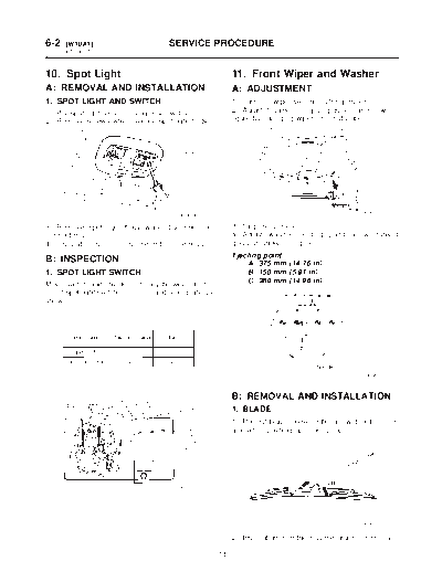
Image preview - the first page of the document
>> Download MSA5TCD98L21291 documenatation <<
Text preview - extract from the document
6-2   [W10A1]                          SERVICE PROCEDURE
10. Spot Light


10. Spot Light                                               11. Front Wiper and Washer
A: REMOVAL AND INSTALLATION                                  A: ADJUSTMENT
1. SPOT LIGHT AND SWITCH                                     1) Turn the wiper switch to OFF position.
1) Pry spot light lens off using a screwdriver.              2) Adjust blades in original position as shown in
2) Remove screws which secure spot light body.               figure by changing wiper arm installation.


                                          B6M0346                                                    B6M0907A


3) Remove spot light body while disconnecting                3) Stop the vehicle.
connector(s).                                                4) Adjust washer ejecting point on windshield
4) Installation is in the reverse order of removal.          glass as shown in figure.
                                                             Ejecting point:
B: INSPECTION                                                    A: 375 mm (14.76 in)
1. SPOT LIGHT SWITCH                                             B: 150 mm (5.91 in)
Move switch and check continuity between termi-                  C: 380 mm (14.96 in)
nal of spot light switch connector and steel plate as
shown.


                                                                                                      G6M0116


                                                             B: REMOVAL AND INSTALLATION
                                                             1. BLADE
                                                             1) Pull out blade following the arrow direction from
                                                             arm while pushing up locking clip.


                                         B6M0838A


                                                                                                     B6M0107A

                                                             2) Installation is in the reverse order of removal.

                                                        18
◦ Jabse Service Manual Search 2026 ◦ Jabse Pravopis ◦ onTap.bg ◦ Other service manual resources online : Fixya ◦ eServiceinfo