Service Manuals, User Guides, Schematic Diagrams or docs for : . Car Manuals Subaru Legacy 1995-1999 Approved Subaru Legacy 1998 1998 Service Manual MECHANICAL COMPONENTS SECTION PEDAL SYSTEM AND CONTROL CABLES MSA5TCD98L21141
<< Back | HomeMost service manuals and schematics are PDF files, so You will need Adobre Acrobat Reader to view : Acrobat Download Some of the files are DjVu format. Readers and resources available here : DjVu Resources
For the compressed files, most common are zip and rar. Please, extract files with Your favorite compression software ( WinZip, WinRAR ... ) before viewing. If a document has multiple parts, You should download all, before extracting.
Good luck. Repair on Your own risk. Make sure You know what You are doing.
Image preview - the first page of the document
>> Download MSA5TCD98L21141 documenatation <<
Text preview - extract from the document
4-5   [W2A0]                        SERVICE PROCEDURE
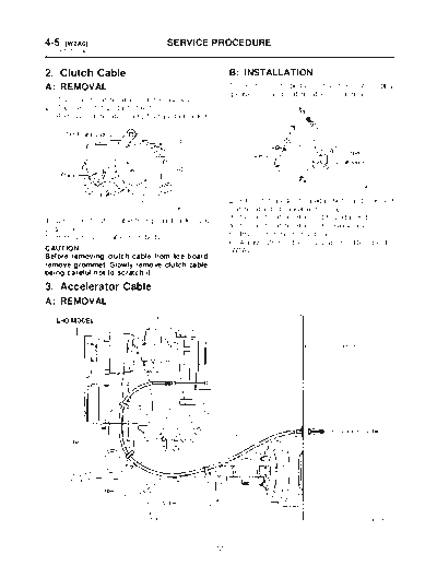
2. Clutch Cable


2. Clutch Cable                                          B: INSTALLATION
A: REMOVAL                                               1) Clean clutch pedal fitting hole, and apply
                                                         grease. Connect clutch cable to clutch pedal.
1) Disconnect clutch cable from release lever.
2) Depress clutch pedal to the floor.
3) Remove clutch cable clamp from pedal bracket.


                                                                                               G4M0332

                                                         2) Fit clutch pedal to pedal bolt, and connect
                                      B4M0160A           clutch cable to bracket with clamp.
4) Disconnect clutch cable from pedal bracket and        3) Connect clutch cable end to pedal end.
pedal end.                                               4) Connect clutch cable from release lever.
5) Remove clutch cable from body.                        5) Install grommet to toe board.
                                                         6) Adjust after cable installation.
Before removing clutch cable from toe board,
remove grommet. Slowly remove clutch cable,
being careful not to scratch it.

3. Accelerator Cable
A: REMOVAL


                                                                                                 B4M0768B


                                                    12
                                   SERVICE PROCEDURE                                         [W3B0] 4-5
                                                                                       3. Accelerator Cable


                                                                                                  B4M1157C


1) Disconnect accelerator cable from connector          7) Working inside engine compartment, remove
inside engine compartment first.                        the casing cap out of the toe board by turning it
2) Remove lock nut from accelerator cable               clockwise.
bracket.
3) Separate accelerator cable (1) from bracket,
then unlock inner cable.


                                                                                                G4M0335

                                                        8) Pull out the cable from the toe board hole.
                                      B4M1185A
                                                        B: INSTALLATION
4) Remove cable end from throttle cam using your
                                                        1) Installation is in the reverse order of removal
fingertips.
                                                        procedures.
CAUTION:                                                CAUTION:
Be careful not to bend inner cable.
◦ Jabse Service Manual Search 2026 ◦ Jabse Pravopis ◦ onTap.bg ◦ Other service manual resources online : Fixya ◦ eServiceinfo