Service Manuals, User Guides, Schematic Diagrams or docs for : . Car Manuals Subaru Legacy 1995-1999 Approved Subaru Legacy 1998 1998 Service Manual MECHANICAL COMPONENTS SECTION WHEELS AND AXLES MSA5TCD98L21084
<< Back | HomeMost service manuals and schematics are PDF files, so You will need Adobre Acrobat Reader to view : Acrobat Download Some of the files are DjVu format. Readers and resources available here : DjVu Resources
For the compressed files, most common are zip and rar. Please, extract files with Your favorite compression software ( WinZip, WinRAR ... ) before viewing. If a document has multiple parts, You should download all, before extracting.
Good luck. Repair on Your own risk. Make sure You know what You are doing.
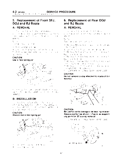
Image preview - the first page of the document
>> Download MSA5TCD98L21084 documenatation <<
Text preview - extract from the document
4-2   [W5A0]                         SERVICE        PROCEDURE
5. Replacement of Front SFJ, DOJ and BJ Boots


5. Replacement of Front SFJ,                             6. Replacement of Rear DOJ
DOJ and BJ Boots                                         and BJ Boots
A: REMOVAL                                               A: REMOVAL
1) Disconnect ground cable from battery.                 1) Disconnect ground cable from battery.
2) Jack-up vehicle, support it with safety stands        2) Lift-up vehicle, and remove rear wheel cap and
(rigid racks), and remove front wheel cap and            wheels.
wheels.                                                  NOTE:
NOTE:                                                    Axle nut need not be removed.
Do not remove axle nut.                                  3) Remove ABS sensor clamps and parking brake
3) Remove stabilizer link.                               cable bracket.
4) Disconnect transverse link from housing.              4) Disconnect stabilizer link from lateral link.
5) Remove spring pin which secures transmission          5) Remove bolts which secure lateral link assem-
spindle to DOJ/SFJ.                                      bly to rear housing.
CAUTION:                                                 6) Remove bolts which secure trailing link assem-
Use a new spring pin.                                    bly to rear housing.
                                                         7) Remove crossmember reinforcement lower
                                                         from crossmember (4 door model only).
                                                         8) Remove DOJ from rear differential using ST.
                                                         (Except 2200 cc AT vehicles)
                                                         ST 28099PA100 DRIVE SHAFT REMOVER
                                                         CAUTION:
                                                         Do not remove circlip attached to inside of dif-
                                                         ferential.


                                         G4M0279

6) Remove SFJ, DOJ and BJ boots from drive
shaft.  or

B: INSTALLATION
1) Install SFJ, DOJ and BJ boots to drive shaft.
 or                                                  G4M0994
2) Install DOJ/SFJ on transmission spindle and
drive spring pin into place.                             CAUTION:
                                                         Be careful not to damage side bearing retainer.
CAUTION:
                                                         Always use bolt as shown in figure, as support-
Always use a new spring pin.
                                                         ing point for ST during removal.
                                                         ST   28099PA100    DRIVE SHAFT REMOVER


                                         G4M0279

3) Connect transverse link to housing.                                                         G4M0995
4) Install stabilizer link.

                                                    42
                                      SERVICE PROCEDURE                                         [W6B0] 4-2
                                                                      6. Replacement of Rear DOJ and BJ Boots


9) Remove DOJ from rear differential using tire             3) Using ST, install DOJ into differential.
lever. (2200 cc AT vehicles)                                ST 28099PA090 SIDE OIL SEAL PROTEC-
                                                                                 TOR
NOTE:
The side spline shaft circlip comes out together
with the shaft.


                                                                                                    B4M0549A

                                                            4) Insert DOJ spline end into bore of side oil seal,
                                         G3M0257            and remove ST.
                                                            CAUTION:
CAUTION:                                                    Do not allow DOJ splines to damage side oil
When removing the DOJ from the rear                         seal.
differential, fit tire lever to the bolt as shown in
                                                            ST   28099PA090     SIDE OIL SEAL PROTEC-
figure so as not to damage the axle shaft
                                                                                TOR
holder.


                                                                                                    B4M0550A
                                         G3M0045
                                                            5) Align DOJ and differential splines.
10) Remove DOJ and BJ boots from drive shaft.               6) Push housing to insert DOJ into differential.

                                                            NOTE:
B: INSTALLATION                                             Make sure DOJ is inserted properly.

1) Install DOJ and BJ boots to drive shaft.

2) Replace circlips from DOJ spline with new one.
(2200 cc AT vehicles only)


                                                                                                     G3M0050


                                                            CAUTION:
                                                            Discard old self-locking nut. Replace with a
                                                            new one.
                                                            7) Connect rear housing assembly to trailing link
                                                            assembly, and tighten self-locking nut.
                                                            8) Connect rear housing assembly to lateral link

                                                       43
4-2    [W7A0]                     SERVICE PROCEDURE
7. Full Wheel Cap


assembly, and tighten self-locking nut.                7. Full Wheel Cap
9) Connect stabilizer link to lateral link.
10) Install crossmember reinforcement lower to         A: REMOVAL
crossmember (4 door model only).
                                                       Pry off the full wheel cap with a wheel cap remover
11) Install ABS sensor clamps and parking brake
                                                       inserted between openings in the cap.
cable bracket.


                                                                                                B4M0051


                                                       B: INSTALLATION
                                                       Align the valve hole in the wheel cap with the valve
                                                       on the wheel and secure the wheel cap by tapping
                                                       four points by hand.


                                                  44
◦ Jabse Service Manual Search 2026 ◦ Jabse Pravopis ◦ onTap.bg ◦ Other service manual resources online : Fixya ◦ eServiceinfo