Service Manuals, User Guides, Schematic Diagrams or docs for : . Car Manuals Subaru Legacy 1995-1999 Approved Subaru Legacy 1998 1998 Service Manual TRANSMISSION AND DIFFERENTIAL SECTION AUTOMATIC TRANSMISSION AND DIFFERENTIAL MSA5TCD98L21027
<< Back | HomeMost service manuals and schematics are PDF files, so You will need Adobre Acrobat Reader to view : Acrobat Download Some of the files are DjVu format. Readers and resources available here : DjVu Resources
For the compressed files, most common are zip and rar. Please, extract files with Your favorite compression software ( WinZip, WinRAR ... ) before viewing. If a document has multiple parts, You should download all, before extracting.
Good luck. Repair on Your own risk. Make sure You know what You are doing.
Image preview - the first page of the document
>> Download MSA5TCD98L21027 documenatation <<
Text preview - extract from the document
                                    SERVICE PROCEDURE                                               [W18B0] 3-2
                                                                                                    18. High Clutch


18. High Clutch
A: DISASSEMBLY


                                                                                                              S3M0041A


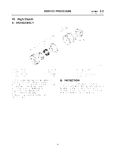
(1)   High clutch drum              (5)   Spring retainer                      (9)    Retaining plate
(2)   Lathe cut seal ring           (6)   Snap ring                            (10)   Snap ring
(3)   High clutch piston            (7)   Driven plate                         (11)   Thrust needle bearing
(4)   Lathe cut seal ring           (8)   Drive plate                          (12)   High clutch hub

1) Remove the snap ring, and take out the retain-           B: INSPECTION
ing plate, drive plates, and driven plates.
2) Using the ST1, ST2 and ST3, remove the snap              1) Drive plate facing for wear and damage
ring and take out the spring retainer.                      2) Snap ring for wear, return spring for setting and
ST1 398673600 COMPRESSOR                                    breakage, and spring retainer for deformation
ST2 398177700 INSTALLER                                     3) Lathe cut seal rings (large) (small) for damage
ST3 399893600 PLIERS                                        4) Piston check ball for smooth operation
3) Apply compressed air to the clutch drum to
remove the piston.


                                                      89
3-2   [W18C0]                         SERVICE PROCEDURE
18. High Clutch


C: ASSEMBLY


                                                                                                          S3M0041B


(1)   High clutch drum                (5)   Spring retainer                (9)    Retaining plate
(2)   Lathe cut seal ring             (6)   Snap ring                      (10)   Snap ring
(3)   High clutch piston              (7)   Driven plate                   (11)   Thrust needle bearing
(4)   Lathe cut seal ring             (8)   Drive plate                    (12)   High clutch hub

1) Using the ST1, ST2 and ST3 as those used in                        Available retaining plates
disassembling, assemble the piston, spring                      Part No.                 Thickness mm (in)
retainer, and snap ring.                                      31567AA190                     3.6 (0.142)
ST1 398673600 COMPRESSOR                                      31567AA200                     3.8 (0.150)
ST2 398177700 INSTALLER                                       31567AA210                     4.0 (0.157)
ST3 399893600 PLIERS                                          31567AA220                     4.2 (0.165)
2) Install the driven plate (thinner), drive plates,          31567AA230                     4.4 (0.173)
driven plates (thicker), and retaining plate in that          31567AA240                     4.6 (0.181)
order. Then attach the snap ring.                             31567AA250                     4.8 (0.189)
                                                              31567AA260                     5.0 (0.197)
3) Checking operation:
Apply compressed air intermittently to the oil hole,
and check the high clutch for smooth operation.
4) Measuring clearance (Retaining plate selec-
tion):
NOTE:
Before measuring clearance, place the same thick-
ness of shim on both sides to prevent retaining
plate from tilting.
Standard value:
    1.8 -- 2.2 mm (0.071 -- 0.087 in)
Allowable limit:
    2.6 mm (0.102 in)


                                                        90
◦ Jabse Service Manual Search 2026 ◦ Jabse Pravopis ◦ onTap.bg ◦ Other service manual resources online : Fixya ◦ eServiceinfo