Service Manuals, User Guides, Schematic Diagrams or docs for : . Car Manuals Subaru Legacy 1995-1999 Approved Subaru Legacy 1999 1999 Service Manual ENGINE SECTION ENGINE (DOHC) MSA5TCD99L54
<< Back | HomeMost service manuals and schematics are PDF files, so You will need Adobre Acrobat Reader to view : Acrobat Download Some of the files are DjVu format. Readers and resources available here : DjVu Resources
For the compressed files, most common are zip and rar. Please, extract files with Your favorite compression software ( WinZip, WinRAR ... ) before viewing. If a document has multiple parts, You should download all, before extracting.
Good luck. Repair on Your own risk. Make sure You know what You are doing.
Image preview - the first page of the document
>> Download MSA5TCD99L54 documenatation <<
Text preview - extract from the document
2-3b     [W4A1]                   SERVICE PROCEDURE
4. Cylinder Head


4. Cylinder Head                                       5) Remove intake manifold assembly and gasket.
                                                       6) Remove camshaft position sensor.
A: REMOVAL                                             7) Remove timing belt, camshaft sprockets and
1. RELATED PARTS                                       related parts.

1) Remove V-belt.                                      8) Remove rocker cover, camshafts and related
2) Remove generator, air conditioner compressor        parts.
and brackets.
3) Remove hoses and tubes from cylinder block.
4) Disconnect each connector and/or remove con-
nector bracket.
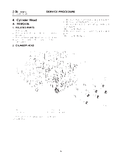
2. CYLINDER HEAD


                                                                                             S2M0421A


(1) Bolt                          (3) Cylinder head
(2) Cylinder head bolt            (4) Cylinder head gasket

1) Remove oil level gauge guide attaching bolt
(LH side only).


                                                  36
                                   SERVICE PROCEDURE                                          [W4B0] 2-3b
                                                                                             4. Cylinder Head


2) Remove cylinder head bolts in alphabetical            3) While tapping cylinder head with a plastic
sequence shown in figure.                                hammer, separate it from cylinder block.
CAUTION:                                                 Remove bolts (A) and (D) to remove cylinder head.
Leave bolts (A) and (D) engaged by three or
four threads to prevent cylinder head from fall-
ing.


                                                                                                   B2M1397C

                                                         4) Remove cylinder head gasket.
                                                         5) Similarly, remove right-hand cylinder head.
                                      B2M1397C


B: DISASSEMBLY


                                                                                                      S2M0420A


(1) Valve shim                      (4) Valve retainer                     (7) Valve spring seat
(2) Valve lifter                    (5) Valve spring                       (8) Intake valve
(3) Valve retainer key              (6) Valve oil seal                     (9) Exhaust valve

1) Remove valve shims and valve lifters.


                                                    37
2-3b     [W4C1]                     SERVICE PROCEDURE
4. Cylinder Head


2) Compress the valve spring and remove the              2) Measure the warping of the cylinder head sur-
valve spring retainer key. Remove each valve and         face that mates with crankcase by using a straight
valve spring.                                            edge and thickness gauge.
ST1 498267600 CYLINDER HEAD TABLE                        If the warping exceeds 0.05 mm (0.0020 in),
ST2 499718000 VALVE SPRING REMOVER                       regrind the surface with a surface grinder.
CAUTION:                                                 Warping limit:
◦ Jabse Service Manual Search 2026 ◦ Jabse Pravopis ◦ onTap.bg ◦ Other service manual resources online : Fixya ◦ eServiceinfo