Service Manuals, User Guides, Schematic Diagrams or docs for : . Car Manuals Subaru Legacy 1995-1999 Approved Subaru Legacy 1999 1999 Service Manual ENGINE SECTION ENGINE (SOHC) MSA5TCD99L41
<< Back | HomeMost service manuals and schematics are PDF files, so You will need Adobre Acrobat Reader to view : Acrobat Download Some of the files are DjVu format. Readers and resources available here : DjVu Resources
For the compressed files, most common are zip and rar. Please, extract files with Your favorite compression software ( WinZip, WinRAR ... ) before viewing. If a document has multiple parts, You should download all, before extracting.
Good luck. Repair on Your own risk. Make sure You know what You are doing.
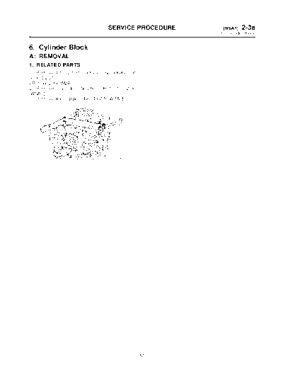
Image preview - the first page of the document
>> Download MSA5TCD99L41 documenatation <<
Text preview - extract from the document
                                 SERVICE PROCEDURE    [W6A1] 2-3a
                                                     6. Cylinder Block


6. Cylinder Block
A: REMOVAL
1. RELATED PARTS
1) Remove timing belt, camshaft sprockets and
related parts.

2) Remove cylinder heads.
3) Remove water pipe.


                                   B2M2638


                                                51
2-3a    [W6A2]                       SERVICE PROCEDURE
6. Cylinder Block


2. OIL PUMP AND WATER PUMP


                                                                                       B2M1767A


(1) Clutch housing cover (MT         (4)   Oil separator cover   (8)    Oil pan
    vehicles only)                   (5)   Water by-pass pipe    (9)    Oil strainer
(2) Flywheel (MT vehicles only)      (6)   Water pump            (10)   Baffle plate
(3) Drive plate (AT vehicles only)   (7)   Oil pump              (11)   Oil filter


                                                       52
                                   SERVICE PROCEDURE                                       [W6A2] 2-3a
                                                                                          6. Cylinder Block


1) Remove clutch housing cover (MT vehicles             7) Removal of oil pan
only).                                                     (1) Turn cylinder block with #2 and #4 piston
2) Remove flywheel (MT vehicles only) or drive             sides facing upward.
plate (AT vehicles only).                                  (2) Remove bolts which secure oil pan to cylin-
Using ST, lock crankshaft.                                 der block.
ST 498497100 CRANKSHAFT STOPPER                            (3) Insert a oil pan cutter blade between cylin-
                                                           der block-to-oil pan clearance and remove oil
                                                           pan.
                                                        CAUTION:
                                                        Do not use a screwdriver or similar tool in
                                                        place of oil pan cutter.


                                      G2M0776


                                                                                                G2M0163

                                                        8) Remove oil strainer stay.
                                                        9) Remove oil strainer.
                                                        10) Remove baffle plate.
                                                        11) Remove oil filter using ST.
                                     B2M0706A           ST 498187300 OIL FILTER WRENCH
3) Remove oil separator cover.
4) Remove water by-pass pipe for heater.
5) Remove water pump.
6) Remove oil pump from cylinder block.
Use a flat-bladed screwdriver as shown in figure
when removing oil pump.
CAUTION:
Be careful not to scratch the mating surface of
cylinder block and oil pump.
                                                                                               B2M2611A


                                      G2M0162


                                                   53
2-3a    [W6B1]                   SERVICE PROCEDURE
6. Cylinder Block


B: DISASSEMBLY
1. PISTON PIN AND CYLINDER BLOCK CONNECTING BOLT


                                                                                                     B2M1180A


(1) Service hole plug            (3) Circlip                              (5) Service hole cover
(2) Gasket                       (4) Piston pin

1) Remove service hole cover and service hole          2) Rotate crankshaft to bring #1 and #2 pistons to
plugs using hexagon wrench [14 mm (0.55 in)].          bottom dead center position, then remove piston
                                                       circlip through service hole of #1 and #2 cylinders.


                                    B2M2620
                                                                                                   G2M0165


                                                  54
                                    SERVICE PROCEDURE                                       [W6B2] 2-3a
                                                                                           6. Cylinder Block


3) Draw out piston pin from #1 and #2 pistons            4) Similarly remove piston pins from #3 and #4
using ST.                                                pistons.
ST 499097700 PISTON PIN REMOVER                          5) Remove bolts which connect cylinder block on
CAUTION:                                                 the side of #2 and #4 cylinders.
Be careful not to confuse original combination           6) Back off bolts which connect cylinder block on
of piston, piston pin and cylinder.                      the side of #1 and #3 cylinders two or three turns.


                                      G2M0166


2. CYLINDER BLOCK


                                                                                                   B2M2408A


(1) Cylinder block                  (3) Crankshaft                         (5) Piston
(2) Rear oil seal                   (4) Crankshaft bearing

1) Set up cylinder block so that #1 and #3 cylin-        CAUTION:
ders are on the upper side, then remove cylinder         When separating cylinder block, do not allow
block connecting bolts.                                  the connecting rod to fall and damage the cyl-
2) Separate left-hand and right-hand cylinder            inder block.
blocks.                                                  3) Remove rear oil seal.


                                                    55
2-3a    [W6B3]                       SERVICE PROCEDURE
6. Cylinder Block


4) Remove crankshaft together with connecting               6) Draw out each piston from cylinder block using
rod.                                                        wooden bar or hammer handle.
5) Remove crankshaft bearings from cylinder
                                                            CAUTION:
block using hammer handle.
                                                            Do not confuse combination of piston and cyl-
CAUTION:                                                    inder.
Do not confuse combination of crankshaft
bearings. Press bearing at the end opposite to
locking lip.
3. CRANKSHAFT AND PISTON


                                                                                                     B2M1320I


(1) Connecting rod cap               (3) Top ring                             (5) Oil ring
(2) Connecting rod bearing           (4) Second ring                          (6) Circlip

1) Remove connecting rod cap.                               3) Inspect crankcase surface that mates with cyl-
2) Remove connecting rod bearing.                           inder head for warping by using a straight edge,
CAUTION:                                                    and correct by grinding if necessary.
Arrange removed connecting rod, connecting                  Warping limit:
rod cap and bearing in order to prevent confu-                  0.05 mm (0.0020 in)
sion.                                                       Grinding limit:
3) Remove piston rings using the piston ring                    0.1 mm (0.004 in)
expander.                                                   Standard height of cylinder block:
4) Remove the oil ring by hand.                                 201.0 mm (7.91 in)
CAUTION:
Arrange the removed piston rings in good
order to prevent confusion.
5) Remove circlip.

C: INSPECTION
1. CYLINDER BLOCK
1) Visually check for cracks and damage.
Especially, inspect important parts by means of red
lead check.
2) Check the oil passages for clogging.


                                                       56
                                     SERVICE PROCEDURE                                       [W6C2] 2-3a
                                                                                            6. Cylinder Block


2. CYLINDER AND PISTON                                    2) How to measure the inner diameter of each
                                                          cylinder
1) The cylinder bore size is stamped on the cylin-
                                                          Measure the inner diameter of each cylinder in
der block's front upper surface.
                                                          both the thrust and piston pin directions at the
CAUTION:                                                  heights shown in the figure, using a cylinder bore
Measurement should be performed at a tem-                 gauge.
perature 20
◦ Jabse Service Manual Search 2026 ◦ Jabse Pravopis ◦ onTap.bg ◦ Other service manual resources online : Fixya ◦ eServiceinfo