Service Manuals, User Guides, Schematic Diagrams or docs for : . Car Manuals Subaru Legacy 1995-1999 Approved Subaru Legacy 1999 1999 Service Manual TRANSMISSION AND DIFFERENTIAL SECTION AUTOMATIC TRANSMISSION AND DIFFERENTIAL MSA5TCD99L202

<< Back | Home

Most service manuals and schematics are PDF files, so You will need Adobre Acrobat Reader to view : Acrobat Download Some of the files are DjVu format. Readers and resources available here : DjVu Resources
For the compressed files, most common are zip and rar. Please, extract files with Your favorite compression software ( WinZip, WinRAR ... ) before viewing. If a document has multiple parts, You should download all, before extracting.
Good luck. Repair on Your own risk. Make sure You know what You are doing.


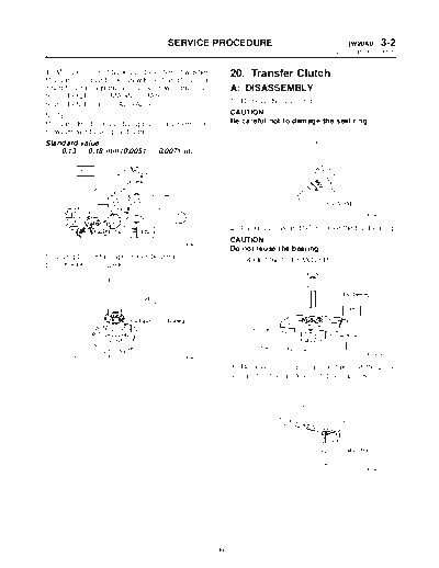
Image preview - the first page of the document
MSA5TCD99L202


>> Download MSA5TCD99L202 documenatation <<

Text preview - extract from the document
                                       SERVICE PROCEDURE                                    [W20A0] 3-2
                                                                                        20. Transfer Clutch


4) Measurement of backlash (Selection of washer)         20. Transfer Clutch
Measure the gear backlash with ST1 and ST2, and
insert ST2 through the access window of the case.        A: DISASSEMBLY
ST1 498247001 MAGNET BASE
ST2 498247100 DIAL GAUGE                                 1) Remove the seal ring.

NOTE:                                                    CAUTION:
Measure the backlash by applying a pinion tooth          Be careful not to damage the seal ring.
between two bevel gear teeth.
Standard value:
    0.13 -- 0.18 mm (0.0051 -- 0.0071 in)


                                                                                                G3M0493

                                                         2) Using a press and ST, remove the ball bearing.
                                                         CAUTION:
                                         G3M0491
                                                         Do not reuse the bearing.
5) Using ST, install taper roller bearing.               ST   498077600    REMOVER
ST 398487700 DRIFT


                                                                                                G3M0494
                                         G3M0492

                                                         3) Remove the snap ring, and take out the pres-
                                                         sure plate, drive plates, and driven plates.


                                                                                                G3M0495


                                                    99
3-2   [W20B0]                            SERVICE PROCEDURE
20. Transfer Clutch


4) Remove the snap ring with ST1, ST2 and ST3,             2) Install return spring to transfer piston.
and take out the return spring and transfer clutch
piston seal.
ST1 399893600 PLIERS
ST2 398673600 COMPRESSOR
ST3 398623600 SEAT


                                                                                                     B3M1177A

                                                           3) Install transfer clutch piston seal.


                                          B3M1415A

5) Apply compressed air to the rear drive shaft to
remove the piston.


                                                                                                     B3M1401A

                                                           4) Install ST to rear drive shaft.
                                                           ST 499257300 SNAP RING OUTER GUIDE


                                          G3M0497


B: INSPECTION
1) Check the drive plate facing for wear and dam-
age.
2) Check the snap ring for wear, return spring for
permanent set and breakage, and return spring for
                                                                                                     B3M1402A
deformation.
3) Check the lathe cut ring for damage.                    5) Install snap ring to ST.
                                                           ST 499257300 SNAP RING OUTER GUIDE
C: ASSEMBLY
1) Install the transfer clutch piston.


                                                                                                     B3M1180A


                                          B3M1400A


                                                     100
                                      SERVICE PROCEDURE                                             [W20C0] 3-2
                                                                                                20. Transfer Clutch


6) Using ST1 and ST2, install snap ring to rear              9) Check the clearance.
drive shaft.                                                 NOTE:
NOTE:                                                        Before measuring clearance, place the same thick-
After installing snap ring, remove ST1 and ST2.              ness of shim on both sides to prevent pressure
ST1   499257300     SNAP RING OUTER GUIDE                    plate from tilting.
ST2   499247400     INSTALLER                                If the clearance is not within the specified range,
                                                             select a proper pressure plate.
                                                             Standard value:
                                                                 0.2 -- 0.6 mm (0.008 -- 0.024 in)
                                                             Allowable limit:
                                                                 1.6 mm (0.063 in)


                                        B3M1181A

7) Install the driven plates, drive plates, pressure
plate and snap ring.


                                                                                                         G3M0503


                                                                            Available pressure plates
                                                                      Part No.                Thickness mm (in)
                                                                    31593AA151                    3.3 (0.130)
                                                                    31593AA161                    3.7 (0.146)
                                                                    31593AA171                    4.1 (0.161)
                                                                    31593AA181                    4.5 (0.177)
                                        B3M1182A
                                                             10) Press-fit the ball bearing with ST.
8) Apply compressed air to see if the assembled              ST 899580100 INSTALLER
parts move smoothly.


                                                                                                         G3M0505
                                         G3M0502


                                                       101
3-2   [W21A0]                         SERVICE PROCEDURE
21. Transfer Valve Body


11) Coat the seal ring with vaseline, and install it         21. Transfer Valve Body
in the seal ring groove of the shaft.
CAUTION:                                                     A: DISASSEMBLY
Do not expand the seal ring excessively when                 1) Separate duty solenoid C (transfer) and trans-
installing.                                                  fer valve body.
ST    899580100    INSTALLER                                 2) Remove the stopper plate and pry out the plug
                                                             with a screwdriver. Then extract the spring and
                                                             transfer control valve together.
                                                             CAUTION:
                                                             Be careful not to damage the valve and valve
                                                             body.


                                         G3M0493


                                                                                                   B3M1183A

                                                                (A)   Transfer valve body
                                                                (B)   Return spring
                                                                (C)   Transfer control valve
                                                                (D)   Plug
                                                                (E)   Stopper plate

                                                             B: INSPECTION
                                                             Check each component for harmful cuts, damage,
                                                             or other faults.

                                                             C: ASSEMBLY
                                                             To assemble, reverse the removal sequence.
                                                             NOTE:
                                                             Make sure the valve slides smoothly after assem-
                                                             bling.


                                                       102


◦ Jabse Service Manual Search 2026 ◦ Jabse PravopisonTap.bg ◦ Other service manual resources online : FixyaeServiceinfo