Service Manuals, User Guides, Schematic Diagrams or docs for : . Car Manuals Subaru Legacy 2000-2003 Approved Subaru Legacy 2000 2000 Service Manual ENGINE SECTION Engine Lubrication System MSA5TCD00L16130

<< Back | Home

Most service manuals and schematics are PDF files, so You will need Adobre Acrobat Reader to view : Acrobat Download Some of the files are DjVu format. Readers and resources available here : DjVu Resources
For the compressed files, most common are zip and rar. Please, extract files with Your favorite compression software ( WinZip, WinRAR ... ) before viewing. If a document has multiple parts, You should download all, before extracting.
Good luck. Repair on Your own risk. Make sure You know what You are doing.


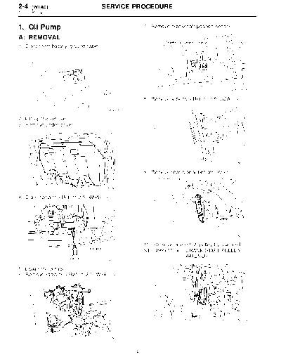
Image preview - the first page of the document
MSA5TCD00L16130


>> Download MSA5TCD00L16130 documenatation <<

Text preview - extract from the document
2-4    [W1A0]                         SERVICE PROCEDURE
1. Oil Pump


1. Oil Pump                                             7) Remove crankshaft position sensor.

A: REMOVAL
1) Disconnect battery ground cable.


                                                                                                B2M1252A

                                                        8) Remove V-belts. 

                                       G6M0095

2) Lift-up the vehicle.
3) Remove under cover.


                                                                                                G2M0286

                                                        9) Remove rear side V-belt tensioner.


                                          B2M2920

4) Drain coolant. 


                                                                                                 S2M0113

                                                        10) Remove crankshaft pulley by using ST.
                                                        ST 499977100 CRANKSHAFT PULLEY
                                                                        WRENCH
                                       B2M2921A

5) Lower the vehicle.
6) Remove radiator. 


                                                                                                 S2M0114


                                          B2M2933


                                                    4
                                    SERVICE PROCEDURE                                     [W1A0] 2-4
                                                                                            1. Oil Pump


11) Remove water pump.             15) Remove oil pump by using flat bladed screw-
                                                        driver.
                                                        CAUTION:
                                                        Be careful not to scratch mating surfaces of
                                                        cylinder block and oil pump.


                                       S2M0022

12) Remove timing belt guide. (MT vehicles only)

                                                                                             G2M0071


                                       S2M0115

13) Remove crankshaft sprocket.


                                       S2M0116

14) Remove bolts which install oil pump onto cyl-
inder block.


                                       S2M0117


                                                    5
2-4    [W1B0]                         SERVICE PROCEDURE
1. Oil Pump


B: DISASSEMBLY                                             C: INSPECTION
Remove screws which secure oil pump cover and              1. TIP CLEARANCE
disassemble oil pump. Inscribe alignment marks
                                                           Measure the tip clearance of rotors. If the clear-
on inner and outer rotors so that they can be
                                                           ance exceeds the limit, replace rotors as a
replaced in their original positions during reassem-
                                                           matched set.
bly.
                                                           Tip clearance:
CAUTION:
                                                             Standard
Before removing relief valve, loosen plug when
                                                                0.04 -- 0.14 mm (0.0016 -- 0.0055 in)
removing oil pump from cylinder block.
                                                             Limit
                                                                0.18 mm (0.0071 in)


                                                                                                  S2M0736A


                                                           2. CASE CLEARANCE
                                                           Measure the clearance between the outer rotor
                                                           and the cylinder block rotor housing. If the clear-
                                                           ance exceeds the limit, replace the rotor.
                                                           Case clearance:
                                                             Standard
                                        S2M0735A
                                                               0.10 -- 0.175 mm (0.0039 -- 0.0069 in)
                                                             Limit
   (A)   Oil seal                                              0.20 mm (0.0079 in)
   (B)   Pump case
   (C)   Inner rotor
   (D)   Outer rotor
   (E)   Pump cover
   (F)   Relief valve
   (G)   Relief spring
   (H)   Plug
   (I)   Washer


                                                                                                  S2M0737A


                                                       6
                                     SERVICE PROCEDURE                                         [W1D0] 2-4
                                                                                                 1. Oil Pump


3. SIDE CLEARANCE                                         D: ASSEMBLY
Measure clearance between oil pump inner rotor            1) Install front oil seal by using ST.
and pump cover. If the clearance exceeds the limit,       ST 499587100 OIL SEAL INSTALLER
replace rotor or pump body.                               CAUTION:
Side clearance:                                           Use a new oil seal.
  Standard
    0.02 -- 0.07 mm (0.0008 -- 0.0028 in)
  Limit
    0.15 mm (0.0059 in)


                                                                                                 S2M0235A

                                                          2) Install inner and outer rotors in their original
                                                          positions.
                                                          3) Install oil relief valve and relief spring.
                                        S2M0738
                                                          4) Install oil pump cover.
                                                          Tightening torque:
4. OIL RELIEF VALVE                                           T1: 5+1/-0 N


◦ Jabse Service Manual Search 2024 ◦ Jabse PravopisonTap.bg ◦ Other service manual resources online : FixyaeServiceinfo