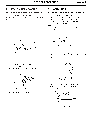
Service Manuals, User Guides, Schematic Diagrams or docs for : . Car Manuals Subaru Legacy 2000-2003 Approved Subaru Legacy 2000 2000 Service Manual MECHANICAL COMPONENTS SECTION HEATER AND VENTILATOR MSA5TCD00L17565
<< Back | HomeMost service manuals and schematics are PDF files, so You will need Adobre Acrobat Reader to view : Acrobat Download Some of the files are DjVu format. Readers and resources available here : DjVu Resources
For the compressed files, most common are zip and rar. Please, extract files with Your favorite compression software ( WinZip, WinRAR ... ) before viewing. If a document has multiple parts, You should download all, before extracting.
Good luck. Repair on Your own risk. Make sure You know what You are doing.
Image preview - the first page of the document

>> Download MSA5TCD00L17565 documenatation <<
Text preview - extract from the document
                                      SERVICE PROCEDURE                                      [W4A0] 4-6
                                                                                             4. Control Unit


3. Blower Motor Assembly                                  4. Control Unit
A: REMOVAL AND INSTALLATION                               A: REMOVAL AND INSTALLATION
1) Disconnect GND cable from battery.                     1) Disconnect GND cable from battery.
2) Remove stopper (A) and then remove glove               2) Remove console box.
box.                                                      3) Set temperature control switch (A) to "FULL
                                                          HOT" and then disconnect temperature control
                                                          cable from bottom of heater unit.
                                                          NOTE:
                                                          Do not attempt to move switch and link during
                                                          installation.


                                                                                                B5M0645A

                                                          4) Remove front cover (A) while disconnecting
                                                          connector.
                                                          5) Remove two screws (B) and then remove cen-
                                                          ter panel (C) while disconnecting connector.
                                        B5M0640A

3) Disconnect blower motor harness connector.
4) Disconnect aspirator pipe (A).
5) Remove blower motor mounting screw.


                                                                                                B6M1209A

                                                          6) Remove fitting screws, and slightly pull radio
                                                          bracket out from center console while disconnect-
                                                          ing connector.
                                        S4M0033A

6) Remove blower motor assembly.
7) Installation is in the reverse order of removal.


                                                                                                 B4M1702


                                                      7
4-6   [W4B1]                          SERVICE PROCEDURE
4. Control Unit


7) Disassemble radio bracket.                              3. FRESH/RECIRC SWITCH
                                                           Check continuity between terminals at each switch
                                                           position.


                                         B4M1703

8) Installation is in the reverse order of removal.
                                                                                                  B4M2245
NOTE:
Before installing control unit, set temperature con-
trol switch to "FULL HOT" position.
B: INSPECTION
1. FAN SWITCH
Check continuity between terminals at each switch
position.


                                         B4M2243


2. MODE ACTUATOR SWITCH
Check continuity between terminals at each switch
position.


                                         B4M2244


                                                       8
◦ Jabse Service Manual Search 2024 ◦ Jabse Pravopis ◦ onTap.bg ◦ Other service manual resources online : Fixya ◦ eServiceinfo