Service Manuals, User Guides, Schematic Diagrams or docs for : . Car Manuals Subaru Legacy 2000-2003 Approved Subaru Legacy 2000 2000 Service Manual MECHANISM AND FUNCTION SECTION Brakes MSA5TCD00L18225
<< Back | HomeMost service manuals and schematics are PDF files, so You will need Adobre Acrobat Reader to view : Acrobat Download Some of the files are DjVu format. Readers and resources available here : DjVu Resources
For the compressed files, most common are zip and rar. Please, extract files with Your favorite compression software ( WinZip, WinRAR ... ) before viewing. If a document has multiple parts, You should download all, before extracting.
Good luck. Repair on Your own risk. Make sure You know what You are doing.
Image preview - the first page of the document

>> Download MSA5TCD00L18225 documenatation <<
Text preview - extract from the document
                            LEGACY (W2260BE_SGML Complete)


4-4       [M6A0]                    MECHANISM AND FUNCTION
6. Anti-lock Brake System (ABS)


6. Anti-lock Brake System (ABS)
A: FEATURE
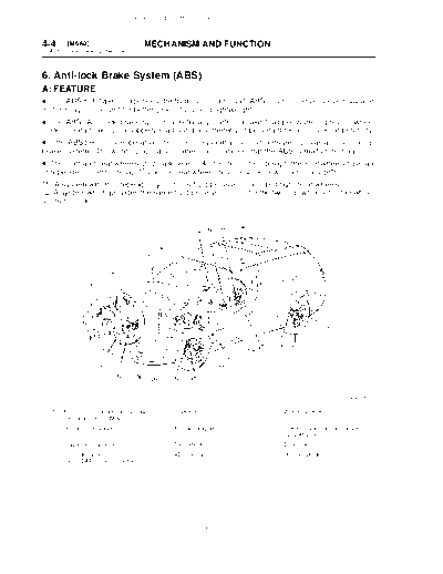
D This ABS 5.3i type incorporates the hydraulic control unit, ABS control module, valve relay and
motor relay in one unit for better productivity and lightweight.
D The ABS (Anti-lock brake system) electrically controls brake fluid pressure to prevent wheel
"lock" during braking on slippery road surfaces, thereby improving directional/steering stability.
D If the ABS becomes inoperative, the fail-safe system activates to ensure it acts as a conventional
brake system. The warning light also comes on to indicate that the ABS is malfunctioning.
D The front-and-rear wheels utilize a 4-sensor, 4-channel control design: the front wheels have an
independent control design*1 and the rear wheels have a select low control design*2.
*1: A system which independently controls fluid pressure to left and right front wheels.
*2: A system which provides the same fluid pressure control for the two rear wheels if either wheel
starts to "lock."


                                                                                               B4H2196A

  (1) ABS control module and hydraulic   (5) G sensor                (9) Wheel cylinder
      control unit (ABSCM & H/U)
  (2) Proportioning valve                (6) ABS warning light      (10) Transmission control module
                                                                         (only AT vehicle)
  (3) Diagnosis connector                (7) Tone wheel             (11) Brake switch
  (4) Data link connector                (8) ABS sensor             (12) Master cylinder
      (for SUBARU select monitor)


                                                          10
                    LEGACY (W2260BE_SGML Complete)


                                         MECHANISM AND FUNCTION                                               [M6B0]     4-4
                                                                                             6. Anti-lock Brake System (ABS)


B: FUNCTIONS OF SENSORS AND ACTUATORS
                        Name                                                           Function
ABS control module and         ABSCM-section         D Calculates to determine the conditions of the wheels and body from the
hydraulic control unit                               wheel speeds and makes a proper decision suitable for the current situa-
(ABSCM & H/U)                                        tion to control the hydraulic unit.
                                                     D In the ABS operation mode, the module outputs a cooperative control
                                                     signal to the AT control module. (AT vehicles only)
                                                     D Whenever the ignition switch is placed at ON, the module makes a self
                                                     diagnosis. When anything wrong is detected, the module cuts off the sys-
                                                     tem.
                                                     D Communicates with the Subaru select monitor.
                               H/U-section           In the ABS operation mode, the H/U changes fluid passages to control the
                                                     fluid pressure of the wheel cylinders in response to an instruction from the
                                                     ABSCM.
                                                     The H/U also constitutes the brake fluid passage from the master cylinder
                                                     to the wheel cylinders together with pipings.
                               Valve relay-section   Serves as a power switch for the solenoid valve and motor relay coil in
                                                     response to an instruction from the ABSCM.
                               Motor relay-section   Serves as a power switch for the pump motor in response to an instruction
                                                     from the ABSCM.
Wheel speed sensor (ABS sensor)                      Detects the wheel speed in terms of a change in the magnetic flux density
                                                     passing through the sensor, converts it into an electrical signal, and out-
                                                     puts the electrical signal to the ABSCM.
Tone wheel                                           Gives a change in the magnetic flux density by the teeth around the tone
                                                     wheel to let the ABS sensor generate an electrical signal.
G sensor                                             Detects a change in G in the longitudinal direction of the vehicle and out-
                                                     puts it to the ABSCM in terms of a change in voltage.
Stop light switch                                    Transmits the information on whether the brake pedal is depressed or not
                                                     to the ABSCM for use as a condition in determining ABS operation.
ABS warning light                                    Alerts the driver to an ABS fault. When the diagnosis connector and diag-
                                                     nosis terminal are connected, the light flashes to indicate a trouble codes
                                                     in response to an instruction from the ABSCM.
AT control module (TCM) (AT vehicles only)           Provides shift controls (fixing the speed at 3rd or changing front and rear
                                                     wheel transmission characteristics) in response to an instruction from the
                                                     ABSCM.


                                                               11
                           LEGACY (W2260BE_SGML Complete)


4-4       [M6B0]                         MECHANISM AND FUNCTION
6. Anti-lock Brake System (ABS)


                                                                                                                  S4H0019A


  (1) ABS control module and hydraulic      (9) Front right outlet solenoid valve   (17) ABS warning light
      control unit
  (2) ABS control module section           (10) Rear left inlet solenoid valve      (18) Stop light switch
  (3) Valve relay                          (11) Rear left outlet solenoid valve     (19) Stop light
  (4) Motor relay                          (12) Rear right inlet solenoid valve     (20) G sensor
  (5) Motor                                (13) Rear right outlet solenoid valve    (21) Front left ABS sensor
  (6) Front left inlet solenoid valve      (14) Transmission control module         (22) Front right ABS sensor
                                                (only AT module)
  (7) Front left outlet solenoid valve     (15) Diagnosis connector                 (23) Rear left ABS sensor
  (8) Front right inlet solenoid valve     (16) Data link connector                 (24) Rear right ABS sensor


                                                             12
             LEGACY (W2260BE_SGML Complete)


                               MECHANISM AND FUNCTION                                    [M6C0]     4-4
                                                                        6. Anti-lock Brake System (ABS)


C: THEORY OF ABS CONTROL
When the brake pedal is depressed during operation, wheel speed as well as vehicle speed de-
creases. The difference which occurs between wheel speed and vehicle speed is called the "slip"
phenomenon. The magnitude of this action is expressed by "slip" the ratio of which is determined
by the following equation:
Slip ratio = Vehicle speed
◦ Jabse Service Manual Search 2024 ◦ Jabse Pravopis ◦ onTap.bg ◦ Other service manual resources online : Fixya ◦ eServiceinfo