Service Manuals, User Guides, Schematic Diagrams or docs for : . Car Manuals Subaru Legacy 2000-2003 Approved Subaru Legacy 2000 2000 Service Manual MECHANISM AND FUNCTION SECTION Emission Control System and Vacuum Fitting MSA5TCD00L18135
<< Back | HomeMost service manuals and schematics are PDF files, so You will need Adobre Acrobat Reader to view : Acrobat Download Some of the files are DjVu format. Readers and resources available here : DjVu Resources
For the compressed files, most common are zip and rar. Please, extract files with Your favorite compression software ( WinZip, WinRAR ... ) before viewing. If a document has multiple parts, You should download all, before extracting.
Good luck. Repair on Your own risk. Make sure You know what You are doing.
Image preview - the first page of the document

>> Download MSA5TCD00L18135 documenatation <<
Text preview - extract from the document
                 LEGACY (W2260BE_SGML Complete)


                                     MECHANISM AND FUNCTION                                          [M7A0]      2-1
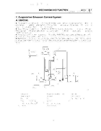
                                                                              7. Evaporative Emission Control System


7. Evaporative Emission Control System
A: GENERAL
D The evaporative emission control system is employed to prevent evaporative fuel from being
discharged into ambient atmosphere. This system includes a canister, purge control solenoid
valve, fuel cut valve, their connecting lines, etc.
D Gasoline vapor evaporated from the fuel in the fuel tank is introduced into the canister through
the evaporation line, and is absorbed on activated carbon in it. A fuel cut valve is also incorporated
on the fuel tank line.
D The purge control solenoid valve is controlled by the ECM and provides optimal purge control
according to the engine condition.
D A pressure control solenoid valve incorporated in the fuel tank evaporation line controls the pres-
sure/vacuum in the fuel tank according to the pressure/vacuum sensed by the fuel tank pressure
sensor.


                                                                                                            B2H3422A


  (1) Fuel gauge                        (7) Pressure control solenoid valve      (13) Fuel tank
  (2) Intake manifold                   (8) Drain valve                          (14) Fuel cut valve
  (3) Throttle body                     (9) Drain filter                         (15) Fuel tank pressure sensor
  (4) Purge control solenoid valve     (10) Shut valve                           (16) Vent valve
  (5) Engine control module (ECM)      (11) Fuel temperature sensor
  (6) Canister                         (12) Fuel level sensor


                                                           13
                      LEGACY (W2260BE_SGML Complete)


2-1     [M7B0]                    MECHANISM       AND FUNCTION
7. Evaporative Emission Control System


B: FUEL CUT VALVE
The fuel cut valve is built onto the evaporation pipe of the fuel tank cap. The rising level of the fuel
from the fuel tank causes the float to move up and close the cap hole so that no fuel can enter
during evaporation line.


                                                                                              B2H3342A


C: FUEL CAP
The relief valve is adopted to prevent the development of vacuum in the fuel tank which may occur
in case of trouble in the fuel vapor line.
In normal condition, the filler pipe is sealed at (A) and at the packing pressed against the filler pipe
end. As vacuum develops in the fuel tank, atmospheric pressure forces the spring down to open
the valve; consequently air is led into the fuel tank controlling the inside pressure.


                                                                                              B2H0395A


                                                  14
            LEGACY (W2260BE_SGML Complete)


                             MECHANISM AND FUNCTION                                  [M7E0]     2-1
                                                             7. Evaporative Emission Control System


D: CANISTER
The canister temporarily stores the evaporation gas. When the purge control solenoid valve is
opened from a signal sent from the ECM, the evaporation gas is sent into the collector chamber
after being mixed with fresh external air.


                                                                                        H2H1164B


E: PURGE CONTROL SOLENOID VALVE
The purge control solenoid valve is on the evaporation line between canister and throttle body.
It is installed at the under side of intake manifold.


                                                                                         B2H0426


                                              15
                       LEGACY (W2260BE_SGML Complete)


2-1     [M7F0]                    MECHANISM         AND FUNCTION
7. Evaporative Emission Control System


F: PRESSURE CONTROL SOLENOID VALVE
The fuel tank pressure control solenoid valve located in the evaporation line between the shut valve
on fuel filler pipe and the canister adjusts the pressure inside the fuel tank under the control of
ECM.
When the tank internal pressure is increased and becomes greater than atmospheric pressure,
the valve is opened to introduce evaporation gas into the canister to purge.
On the other hand, when the tank internal pressure becomes smaller than atmospheric pressure,
external air is taken from the drain valve into the canister.
Also, the pressure control solenoid valve can be electrically closed for system diagnosis.


                                                                                                   B2H1719A


G: DRAIN FILTER
The drain filter is installed at the air inlet port of the vent control solenoid valve to clean the air taken
in the canister through the vent control solenoid valve.


                                                                                                    S2H0874


                                                     16
              LEGACY (W2260BE_SGML Complete)


                                MECHANISM AND FUNCTION                                      [M7I0]     2-1
                                                                    7. Evaporative Emission Control System


H: VENT VALVE
Vent valve is located on the fuel tank. During filling the fuel tank, evaporation gas is introduced to
the canister through vent valve.
When the evaporation pressure overcomes atmospheric pressure and spring force which are ap-
plied to the back side of the diaphragm, the port is opened. Also, the float in the vent valve is to
stop the fuel which is supplied when the tank is filled up. Increasing fuel level raises the float to
close the port.


                                                                                                B2H3424A


I: SHUT VALVE
Shut valve is located on the upper side of fuel filler pipe. When a filler gun is inserted into the filler
pipe, the shut valve is closes the evaporation line.


                                                                                                B2H3423A


                                                   17
                      LEGACY (W2260BE_SGML Complete)


2-1     [M7J0]                    MECHANISM      AND FUNCTION
7. Evaporative Emission Control System


J: DRAIN VALVE
The drain valve is located on the line connecting the drain filter and canister, at a point just below
the drain filter. The drain valve is forcibly closed by a signal from the ECM while the evaporation
system diagnosis is being conducted.


                                                                                             B2H1770


                                                 18
◦ Jabse Service Manual Search 2024 ◦ Jabse Pravopis ◦ onTap.bg ◦ Other service manual resources online : Fixya ◦ eServiceinfo