Service Manuals, User Guides, Schematic Diagrams or docs for : . Car Manuals Toyota 4Runner 1996-2003 Approved SIL techinfo.toyota.com ileaf ewdtmc2 ewdtmpdf ewdsourc 2002 024runne systemci 036cc
<< Back | HomeMost service manuals and schematics are PDF files, so You will need Adobre Acrobat Reader to view : Acrobat Download Some of the files are DjVu format. Readers and resources available here : DjVu Resources
For the compressed files, most common are zip and rar. Please, extract files with Your favorite compression software ( WinZip, WinRAR ... ) before viewing. If a document has multiple parts, You should download all, before extracting.
Good luck. Repair on Your own risk. Make sure You know what You are doing.
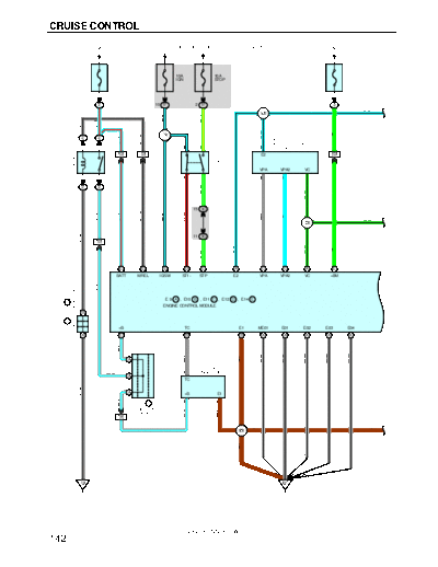
Image preview - the first page of the document
>> Download 036cc documenatation <<
Text preview - extract from the document
CRUISE CONTROL
FROM POWER SOURCE SYSTEM (SEE PAGE 48)
1
20A 10A 10A 15A
EFI IGN STOP ETCS
2
2 10 1F 2 1F 2
L- B
I20
G- Y
B- L
GR- B
L- R
B- L
L- B
G
I12
GR- B
2 2
L- R
A38
ACCEL POSITION
1 5 3 2 2 SENSOR
7 IG1 14 IG1 E2 24 IG1
EFI RELAY
S4
STOP
LIGHT SW
VPA VPA2 VC
2 3 4 1 3 4 1
G- W
2 2
G- B
15 3C
GR- B
W- L
R- B
L- R
B- L
GR
L
G- B
I20
W- B
11 3C
IG1
G- B
L- B
G
G- W
16 E 4 E 15 E 9 D 20 E 11 A 10 C 15 C 25 A 8 E
BATT MREL IGSW ST1- STP E2 VPA VPA2 VC +BM
W- L
JUNCTION CONNECTOR
E 9 A , E10 B , E11 C , E12 D , E14 E
J2 B
ENGINE CONTROL MODULE
A B
J1 A ,
+B TC E1 ME01 E01 E02 E03 E04
A A 1 E 7 B 17 B 6 A 4 A 5 A 7 A 8 A
W- L
D
W- B
W- B
W- B
W- B
W- B
GR
BR
A
D1
D DATA LINK
W- L 11 CONNECTOR 1
A
TC
D
W- B
A +B E1
W- L
J7 A 12 3
JUNCTION
W- L
BR
CONNECTOR
13 II4
BR BR
I20
BR
EB EC
2002 4RUNNER (EWD471U)
142
FROM POWER SOURCE SYSTEM (SEE PAGE 48)
10A
GAUGE
L- B
7 1F 8 1F
B- Y
L- B
T2
THROTTLE 20 II4
1 POSITION SW
10
W- R 7 3 B- Y
W- R II1
W- R
P1
D POSITION SW
[PARK/NEUTRAL
4 2 3 POSITION SW]
17 C A C A
D J7 A , J8 B
4WD ECU
G- B
JUNCTION
CONNECTOR
C/C
F7
16 A B
G- Y
B- Y
G- B
10
3E
(4WD)
GR- B
G- O
8 3E
B- Y
GR
GR
W- R
G- O
(2WD)
4 C 15 A 25 D 17 E 6 E 3 D 13 B 12 B
VTA2 VTA D PI SP1
SPEEDOMETER
CRUISE
E 9 A , E10 B , E11 C , E12 D , E14 E
ENGINE CONTROL MODULE
M+ M- CL+ CL- CCS
9 A 31 A 2 C 8 C 17 A 22 D 17 E 1 D
C27 E , C28 D , C29 B
COMBINATION
GR- L
W- B
BR
METER
G
(SHIELDED)
Y
L
5 16
I20 SP1
CRUISE
C14
(SHIELDED)
CRUISE V18
CANCEL CONTROL SW VSC ECU
G
R
[COMB. SW]
SET/
2 1 COAST
BR M+ M- CL+ CL-
RES/
ACC
T7 4
THROTTLE CONTROL MOTOR A
AND CLUTCH J4
3 JUNCTION
BR BR CONNECTOR
II4
IE
2002 4RUNNER (EWD471U)
143
CRUISE CONTROL
SYSTEM OUTLINE
The cruise control system allows to travel at a constant speed, by the operation of the switch, without having to depress the
accelerator pedal. In this system, the engine throttle valve opening angle is adjusted automatically to control the vehicle at a
constant speed.
1. SET CONTROL
When the SET/COAST SW is operated while traveling with the CRUISE SW ON, the speed when the SW is operated to OFF
(SW released) is memorized, and the vehicle speed is controlled at that speed.
2. COAST CONTROL
When the SET/COAST SW is operated to ON, the motor in the actuator rotates the throttle valve until it is closed fully to
decrease the vehicle speed, and the speed when the SW is operated to OFF is memorized, and the vehicle speed is
controlled at that speed.
Furthermore, every time the SET/COAST SW is operated momentarily (Approx. 0.5 sec.) to ON, the memorized vehicle
speed is decreased by approx. 1.5 km/h.
3. ACCEL CONTROL
When the RESUME/ACCEL SW is operated to ON, the motor in the actuator rotates the throttle valve to open direction to
increase the vehicle speed, and the speed when the SW is operated to OFF is memorized, and the vehicle speed is
controlled at that speed.
Furthermore, every time the RES/ACC SW is operated momentarily (Approx. 0.5 sec.) to ON, the memorized vehicle speed
is increased by approx. 1.5 km/h.
4. MANUAL CANCEL MECHANISM
If any of the following signals are input during cruise control traveling, the magnetic clutch of the actuator is turned off, and
the current to the motor flows in the direction to close the throttle valve, and cancel the cruise control.
(1) Stop light SW is ON (Brake pedal is depressed)
(2) The CANCEL SW of the control SW is ON
(3) CRUISE SW is OFF
5. RESUME CONTROL
After canceling the cruise control (Except when the CRUISE SW is OFF) if the vehicle speed is above the minimum speed
limit (Approx. 40 km/h, 25 mph), operating the RES/ACC SW from OFF to ON will cause the system to accelerate and
resume to the vehicle speed before manual cancellation.
6. OVERDRIVE FUNCTION
The overdrive may be cut on an uphill grade, while traveling with the cruise control.
After the overdrive is cut, if the vehicle seed reaches the overdrive resume speed (Set speed minus 2 km/h), and if the
system determines that the uphill grade has finished, the overdrive will resume after the overdrive timer operation.
7. AUTO CANCEL OPERATION
If any of the following conditions is encountered, the cruise control is automatically cancelled.
The stop light SW wiring is faulty or short-circuited.
The vehicle speed signal is faulty.
The electronically controlled throttle malfunctions.
SERVICE HINTS
E9 (A), E10 (B), E12 (D), E14 (E) ENGINE AND ECT ECU
(E)15-GROUND : Approx. 12 volts with ignition SW at ON or ST position
(E)16-GROUND : Always approx. 12 volts
(A)4, (A) 5, (A) 6, (A) 7, (A) 8, (B) 17-GROUND: Always continuity
(E)20-GROUND : Approx. 12 volts with stop light SW at on
(D)22-GROUND : Continuity with cruise control SW at on
Approx. 1540 with CANCEL SW on in cruise control SW
Approx. 240 with RES/ACC SW on in cruise control SW
Approx. 630 with SET/COAST SW on in cruise control SW
C14 CRUISE CONTROL SW [COMB. SW]
5-4 : Approx. 1540 with CANCEL SW on
Approx. 240 with RES/ACC SW on
Approx. 630 with SET/COAST SW on
2002 4RUNNER (EWD471U)
144
: PARTS LOCATION
Code See Page Code See Page Code See Page
A38 28 E11 C 31 J8 B 31
C14 30 E12 D 31 P1 29
C27 E 30 E14 E 31 S4 31
C28 D 30 F7 31 T2 29
C29 B 30 J1 A 29 T7 29
D1 28 J2 B 29 V18 31
E9 A 31 J4 31
E10 B 31 J7 A 31
: RELAY BLOCKS
Code See Page Relay Blocks (Relay Block Location)
2 22 Engine Room R/B (Engine Compartment Left)
,,, : JUNCTION BLOCK AND WIRE HARNESS CONNECTOR
,,,
,,,
Code See Page Junction Block and Wire Harness (Connector Location)
1F 24 Cowl Wire and Driver Side J/B (Lower Finish Panel)
3C
26 Cowl Wire and Center J/B (Near the Steering Column Tube)
3E
: CONNECTOR JOINING WIRE HARNESS AND WIRE HARNESS
Code See Page Joining Wire Harness and Wire Harness (Connector Location)
IG1 38 Engine Room Main Wire and Cowl Wire (Left Kick Panel)
II1
40 Engine Wire and Cowl Wire (On the Glove Box)
II4
: GROUND POINTS
Code See Page Ground Points Location
EB 36 Front Left Fender
EC 36 Intake Manifold Left
IE 38 Cowl Side Panel LH
: SPLICE POINTS
Code See Page Wire Harness with Splice Points Code See Page Wire Harness with Splice Points
I12 40 Cowl Wire I20 40 Engine Wire
2002 4RUNNER (EWD471U)
145
◦ Jabse Service Manual Search 2026 ◦ Jabse Pravopis ◦ onTap.bg ◦ Other service manual resources online : Fixya ◦ eServiceinfo