Service Manuals, User Guides, Schematic Diagrams or docs for : . Car Manuals Toyota 4Runner 1996-2003 Approved SIL techinfo.toyota.com ileaf ewdtmc2 ewdtmpdf ewdsourc 2002 024runne systemci 0394wd
<< Back | HomeMost service manuals and schematics are PDF files, so You will need Adobre Acrobat Reader to view : Acrobat Download Some of the files are DjVu format. Readers and resources available here : DjVu Resources
For the compressed files, most common are zip and rar. Please, extract files with Your favorite compression software ( WinZip, WinRAR ... ) before viewing. If a document has multiple parts, You should download all, before extracting.
Good luck. Repair on Your own risk. Make sure You know what You are doing.
Image preview - the first page of the document
>> Download 0394wd documenatation <<
Text preview - extract from the document
B- R
158
4WD
22
J5
2
1
W- B B- R B- R JUNCTION
II4
CONNECTOR 4WD
D
D5 G- B B- Y
B- R
B- R
6 B
12 B
8 1F
DETECTION SW
(TRANSFER
A
A
A
A
D
NEUTRAL POSITION) (* 1)
10A
J7 A ,
3 B
JUNCTION
P1
GAUGE
CONNECTOR
A/T INDICATOR LIGHT SW
[PARK/NEUTRAL POSITION
P-G
G- B
2
20
J8 B
B
B
A/T P
C
C
SW]
11
1
3
B- R B- R L- Y L- Y B- Y B- Y
E12
14 A
2 C
II1
II4
7 1F
TFN
20A
13
B- L
4WD
C25 A , C26 C , C29 B
7
4WD
COMBINATION METER
1 1J
2
L- R
B B
B A
L4
FROM POWER SOURCE SYSTEM (SEE PAGE 48)
D
W- R
ENGINE CONTROL MODULE
25
J7 A
V18
JUNCTION
II1
10
12
VSC ECU G- W
CONNECTOR
IG
A
A
C
C
GR- B
25
17
L- R
B B
B A
TF
17
W- R W- R
EXI4
D
J7 A , J8 B
3
EXI
JUNCTION
3
G- O
CONNECTOR FROM COMBINATION METER
EXI3
SPD
8
20
P-G
L- R
L- R
W- B
IND2
B- L
R- B
2002 4RUNNER (EWD471U)
D4
21
G- B
DETECTION SW
IND1
(TRANSFER L4
B- L
7
POSITION)
2
1
5
F7
W- B L- R L- R
II4
L4
I20
4WD ECU
19
B- L B- L B- L B- L
I17
I17
ADD
B- L
16
GR- B
C/C
W- B
R- B
7
1
2
6
W- B R- B R- B R- B R- B
II2
I1
P1
I20
D31
DETECTION SW
(TRANSFER 4WD POSITION)
W- B
B- L
* 1 : CENTER DIFF. LOCK
F7
4WD ECU
P2 TL1 TL2 TL3 TM1 TM2 DL GND 2- 4 DL1 DL2 DM1 DM2
18 9 22 8 13 26 7 25 4 10 23 11 24
W- B
L- W
L- Y
L- B
GR
G
Y
P
L
G- W
B- W
LG
P
B- L B- L
12 II4 2 II2 1 II2 24 II4 9 II4
G- W
B- W
B- L
LG
R
21 II4 4 II2 5 II2 11 II4 4 II4
L- W
1 ED2 3 ED2 5 ED2 6 ED2 2 ED2
L- Y
L- B
G
L
5 6 3 7 2
G- W
B- W
G- B
LG
R
M 3 6 2 5 1
+B L1 L2 M1 M2
GND
4 T1 A39 4
GR
2- 4 SELECT MOTOR ADD ACTUATOR
7 1
W- B
W- B
2- 4 SELECT SW
CENTER DIFF.
LOCK SW
Y
C30
4 ED2
T3
8 2
W- B
W- B
W- B
C W- B
C C W- B
I10
J3 C
JUNCTION
CONNECTOR
W- B
6 II2
(TRANSFER H4L POSITION)
Y
W- B
2
DETECTION SW
18 3E
D32
1 3 II2
16 3E
W- B
W- B
W- B
W- B
W- B
A
J9
JUNCTION
CONNECTOR
W- B W- B W- B
I20 I20 I20
IF
2002 4RUNNER (EWD471U)
159
4WD
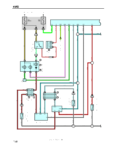
SYSTEM OUTLINE
The 4WD ECU detects the condition of the detection SW ( (Transfer 4WD position), (Transfer H4L Position) ), 2-4 select SW
and the vehicle speed, and controls the 2-4 select motor and center diff. lock SW.
4WD CONTROL
(1) Shift position
The target shift position determined through the condition of the 2-4 select SW and center diff. lock SW, and operates
the 2-4 select motor.
When the 2-4 select SW and the center diff. lock SW are both off, put in to H2 position. At this time, current flows from
the 4WD fuse to TERMINAL 12 of the 4WD ECU to TERMINAL 26 to TERMINAL 2 of the 2-4 select motor to
TERMINAL 7 to TERMINAL 13 of the 4WD ECU to TERMINAL 25 to GROUND, so the 2-4 select motor rotates at H2
position.
When the 2-4 select SW is on and the center diff. lock SW is off, put in to H4 position. At this time, current flows from the
4WD fuse to TERMINAL 12 of the 4WD ECU to TERMINAL 13 to TERMINAL 7 of the 2-4 select motor to TERMINAL 2
to TERMINAL 26 of the 4WD ECU to TERMINAL 25 to GROUND, so the 2-4 select motor rotates at H4 position.
When the 2-4 select SW and the center diff. lock SW are both on, or the 2-4 select SW is off, and the center diff. lock
SW is on, put in to H4L position. When switched from H4F to H4L, current flows from the 4WD fuse to TERMINAL 12 of
the 4WD ECU to TERMINAL 26 to TERMINAL 2 of the 2-4 select motor to TERMINAL 7 to TERMINAL 13 of the 4WD
ECU to TERMINAL 25 to GROUND, so the 2-4 select motor rotates at H4L position. When switched from H2 to H4L,
current flows from the 4WD fuse to TERMINAL 12 of the 4WD ECU to TERMINAL 13 to TERMINAL 7 of the 2-4 select
motor to TERMINAL 2 to TERMINAL 26 of the 4WD ECU to TERMINAL 25 to GROUND, so the 2-4 select motor rotates
at H4L position.
(2) Shift limit control
When the vehicle speed is over 100 km/h, shift change to H4 or H4L mode can not be made. The vehicle speed signal
is input to TERMINAL 3 of the 4WD ECU. At this time, the 4WD indicator light and the center diff. lock indicator light
flashes, and the buzzer installed in the 4WD ECU goes on. This condition can be canceled by decelerating the vehicle
speed to below 100 km/h, or by selecting H2 mode.
(3) Shift control
When the 2-4 select motor will not switch after approximately 3 seconds from shifting (When there are no changes to
the signals to TERMINAL 8, TERMINAL 9 and TERMINAL 22 of the 4WD ECU), the 4WD indicator light and the center
diff. lock indicator light flashes. The cruise control is canceled if in use. When the 2-4 select motor switch is completed,
the indicator lights go off and the cruise control can be set again.
(4) ADD valve control
When switching between 2WD to 4WD, the ADD actuator is controlled to free or lock the ADD. At this time, current flows
from the 4WD fuse to TERMINAL 12 of the 4WD ECU to TERMINAL 23 to TERMINAL 2 of the ADD actuator to
GROUND, or flows from the 4WD fuse to TERMINAL 12 of the 4WD ECU to TERMINAL 10 to TERMINAL 6 of the ADD
actuator to GROUND, so the ADD actuator is controlled.
SERVICE HINTS
F7 4WD ECU
12-GROUND : Approx. 12 volts with ignition SW on
25-GROUND : Always continuity
3-GROUND : Pulse generation with vehicle moving
T3 2-4 SELECT SW
1-2 : Closed with 2-4 select SW on
P1 A/T INDICATOR LIGHT SW [PARK/NEUTRAL POSITION SW]
3-1 : Closed with A/T shift lever at P position
3-7 : Closed with A/T shift lever at D position
: PARTS LOCATION
Code See Page Code See Page Code See Page
A39 28 D31 28 J8 B 31
C25 A 30 D32 28 J9 31
C26 C 30 E12 31 P1 29
C29 B 30 F7 31 T1 29
C30 30 J3 31 T3 31
D4 28 J5 31 V18 31
D5 28 J7 A 31
2002 4RUNNER (EWD471U)
160
,,, : JUNCTION BLOCK AND WIRE HARNESS CONNECTOR
,,,
,,,
Code See Page Junction Block and Wire Harness (Connector Location)
1F
24 Cowl Wire and Driver Side J/B (Lower Finish Panel)
1J
3E 26 Cowl Wire and Center J/B (Near the Steering Column Tube)
: CONNECTOR JOINING WIRE HARNESS AND WIRE HARNESS
Code See Page Joining Wire Harness and Wire Harness (Connector Location)
ED2 36 Engine Wire and Differential Wire (Near the Front Differential)
II1
II2 40 Engine Wire and Cowl Wire (On the Glove Box)
g ( )
II4
: GROUND POINTS
Code See Page Ground Points Location
IF 38 Cowl Side Panel RH
: SPLICE POINTS
Code See Page Wire Harness with Splice Points Code See Page Wire Harness with Splice Points
I1 I17 40 Cowl Wire
40 Cowl Wire
I10 I20 40 Engine Wire
2002 4RUNNER (EWD471U)
161
◦ Jabse Service Manual Search 2026 ◦ Jabse Pravopis ◦ onTap.bg ◦ Other service manual resources online : Fixya ◦ eServiceinfo