Service Manuals, User Guides, Schematic Diagrams or docs for : . Car Manuals Toyota 4Runner 1996-2003 Approved SIL techinfo.toyota.com ileaf ewdtmc2 ewdtmpdf ewdsourc 2002 024runne systemci 056aac
<< Back | HomeMost service manuals and schematics are PDF files, so You will need Adobre Acrobat Reader to view : Acrobat Download Some of the files are DjVu format. Readers and resources available here : DjVu Resources
For the compressed files, most common are zip and rar. Please, extract files with Your favorite compression software ( WinZip, WinRAR ... ) before viewing. If a document has multiple parts, You should download all, before extracting.
Good luck. Repair on Your own risk. Make sure You know what You are doing.
Image preview - the first page of the document
>> Download 056aac documenatation <<
Text preview - extract from the document
AUTOMATIC AIR CONDITIONING
FROM POWER SOURCE SYSTEM (SEE PAGE 48)
1
50A 10A 7. 5A
HEATER GAUGE ECU- B
2
2 5 1E 5 1F 4 1B
R- L
L- R
B- Y
9 3D
B B
R
J1 A , J2 B
JUNCTION
CONNECTOR
C A 2 3D
R- L
L- R
2 2 B- Y
B- Y
1 5
B- Y
4 I10
HEATER
RELAY
4 IJ1
2 3
L- W
B- Y
2 2 2 1
CLUTCH RELAY
A/C MAGNETIC
W- B
Y- R
L- R
A32
4 IG1 11 IG1
7 9 4
Y- R Y- R
L- R
W- B
B- W
B- Y
4 1
L- R 2 1 W- L
I22 M 3B 3B
B6
W- L
J1 A BLOWER MOTOR 2 3B 1 IJ1 2 IJ1 3 IJ1
B- Y
L- R
JUNCTION W- L
CONNECTOR
A 3 4 2 1 G- B
W- G
W- B
LINEAR CONTROLLER
A
SPEED RELAY
+B VM
EXTRA HIGH
BLOWER MOTOR
A
A GND SI
E15
1 2 4 3 25 II4
B14
R- Y
W- B
W- B
W- B
W- G
R- W R- W
W- B 1
I21
A2
A/C MAGNETIC
W- B CLUTCH
W- B
J9
JUNCTION
A CONNECTOR A
A W- B W- B
EB IF
2002 4RUNNER (EWD471U)
212
HEATER CONTROL PANEL SW
A30 B , A31 A
A/C AMPLIFIER
ILL- STX ILL+ CLK IG+ SWD GND DPD 5V BLK
B IG+ HR MGC FR BLW GND PSW AIF AIR TPI
13 A 26 A 10 A 2 B 23 A 16 B 14 A 9 B 6 A 7 A 7 B
R- W
W- B
R- G
G- B
Y- G
Y- R
R- Y
L- R
B- Y
O
V
Y
2 1 3 4
Mfrs Mrec Pt Vz
L- R
RECIRC
B- Y A35
I10 AIR INLET CONTROL
SERVO MOTOR
FRESH
M
B- Y
GND
5
GR
Y- R
O
G- B
1
A/C DUAL PRESSURE SW
B- Y
R- Y
A1
2
R- W
W- B
W- B
B- Y
16 17
W- B W- B W- B W- B
3E 3E I12
2002 4RUNNER (EWD471U)
213
AUTOMATIC AIR CONDITIONING
A30 B , A31 A
A/C AMPLIFIER
S5 TS FACE B/L FOOT F/D DEF AMH AMC
11 A 5 B 4 A 17 A 18 A 19 A 20 A 9 A 8 A
G- W
G- B
P- B
Y- B
R- L
W
R
Y
P
Y
I15
A/C SOLAR SENSOR
2
1
A34
Y
Y
Y Y
I15
GR GR
G- W
G- B
P- B
Y- B
R- L
A37
AIR VENT MODE
CONTROL SERVO MOTOR 4 5 6 7 8
W
R
FACE B/L FOOT F/D DEF
4 2
MH MC
W
R
AIR MIX CONTROL SERVO MOTOR AND
M
Mhot Mcool
A/C WATER TEMP. SENSOR
A
WARM
CONTROL
CIRCUIT
B
COOL
M
B- Y 2 +
A36
W- B 1 -
2002 4RUNNER (EWD471U)
214
Y
GR
6
VZ
G Y
Vz
7
PT
B B B
8 B
TP
Pt
5
SG
Y GR GR GR
1 A
I19
SG
GND
GR
3
1
2
G
G GR GR GR B- L B- L 3 B
I15
26 IG1
19 IG1
TAM
A26
A/C AMBIENT TEMP. SENSOR
GR
1
2
GR B- Y
4 B
TR
I14
1
TW
B- R B- R
A33
A/C ROOM TEMP. SENSOR
6
5
A36
1
2
B- R
GR B- R B W- R
A/C AMPLIFIER
AIR MIX CONTROL SERVO MOTOR AND
6 B
TE
IJ1
IJ1
A/C WATER TEMP. SENSOR
A30 B , A31 A
A14
A/C THERMISTOR
B- R
5 A
TW
2002 4RUNNER (EWD471U)
3
L- B
E14
10 B
ACT
ACT
MODULE
9
L- Y
ENGINE CONTROL
13 B
AC1
AC1
C25 A , C27 E , C28 D
COMBINATION METER
G- O G- O
15 A
3 D
8 3E
6 3E
SPD
A
W- B W- B W- B
17 E
13 A
11 B
IE
VER1
J4
JUNCTION
CONNECTOR
215
AUTOMATIC AIR CONDITIONING
SYSTEM OUTLINE
1. HEATER BLOWER MOTOR OPERATION
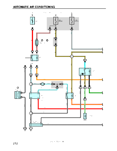
Current is applied at all times through HEATER fuse to TERMINAL 1 of the HEATER relay. When the ignition SW is turned
on, current flows through the GAUGE fuse to TERMINAL 5 of the HEATER relay to TERMINAL 3 to TERMINAL HR of the
A/C amplifier. At the same time, current also flows from GAUGE fuse to TERMINAL IG+ of the A/C amplifier.
Low speed operation
When the blower SW (Heater control panel SW) is pushed to LOW SPEED position, the current to TERMINAL HR of the
A/C amplifier flows to TERMINAL GND of the A/C amplifier to GROUND and turns the HEATER relay on. As a result, the
current to TERMINAL 1 of the HEATER relay flows to TERMINAL 2 of the relay to TERMINAL 2 of the blower motor to
TERMINAL 1 to TERMINAL 2 of the blower resistor (Low) to TERMINAL 1 to GROUND and causes the blower motor to
rotate at low speed.
High speed operation
When the blower SW (Heater control panel SW) is pushed to HIGH SPEED position, the current to TERMINAL HR of the
A/C amplifier flows to TERMINAL GND of the A/C amplifier to GROUND and turns the HEATER relay on. As a result, the
current to TERMINAL 1 of the HEATER relay flows to TERMINAL 2 to TERMINAL 2 of the blower motor to TERMINAL 1
to TERMINAL 4 of the blower motor linear controller to TERMINAL 2 to TERMINAL BLW of the A/C amplifier (Which is
activated when the blower SW is pushed to high speed position) to TERMINAL GND to GROUND without passing
through the blower resistor (Low), causing the blower motor to rotate at high speed.
2. AIR INLET CONTROL SERVO MOTOR OPERATION
(Switching from FRESH to RECIRC)
With the ignition SW turned on, the current flows from GAUGE fuse to TERMINAL IG+ of the A/C amplifier to TERMINAL AIR
to TERMINAL 1 of the air inlet control servo motor to TERMINAL 2 to TERMINAL AIF of the A/C amplifier to TERMINAL
GND to GROUND, the motor rotates and the damper moves to the RECIRC side. when the damper operates with the heater
control panel SW at RECIRC position, the damper position signal is input from TERMINAL 3 of the servo motor to
TERMINAL TPI of the A/C amplifier. As a result, current to the servo motor circuit is cut off by the A/C amplifier, so the
damper stops at that position.
(Switching from RECIRC to FRESH)
With the ignition SW turned on, when the heater control panel SW is switched to the FRESH side, the current flows from
TERMINAL IG+ of the A/C amplifier to TERMINAL AIF to TERMINAL 2 of the air inlet control servo motor to TERMINAL 1 to
TERMINAL AIR of the A/C amplifier to TERMINAL GND to GROUND, The motor rotates and the damper stops at that
position.
3. AIR VENT MODE CONTROL SERVO MOTOR OPERATION
When the ignition SW turned on, the current flows from GAUGE fuse to TERMINAL IG+ of the A/C amplifier.
(Switching from DEF to FACE)
The current flows from TERMINAL FACE of the A/C amplifier to TERMINAL 4 of the air vent mode control servo motor to
TERMINAL 8 to TERMINAL DEF of the A/C amplifier to TERMINAL GND to GROUND. The motor rotates and the damper
moves to the FACE side. When the damper operates with the heater control panel SW at FACE position, the damper
position signal is input from TERMINAL 8 of the servo motor to the TERMINAL DEF of the A/C amplifier. As a result, current
to the servo motor circuit is cut off by the A/C amplifier, so the damper stops at that position.
(Switching from FACE to DEF)
The current flows from TERMINAL DEF of the A/C amplifier to TERMINAL 8 of the air vent control servo motor to TERMINAL
4 to TERMINAL FACE of the A/C amplifier to TERMINAL GND to GROUND, the motor rotates and the damper stops at that
position.
4. AIR MIX CONTROL SERVO MOTOR OPERATION
When the temperature control SW (Heater control panel SW) is turned to the "COOL" side the current flows from TERMINAL
AMC of the A/C amplifier to TERMINAL 2 of the air mix control servo motor to motor to TERMINAL 4 to TERMINAL AMH of
the A/C amplifier to GROUND and the motor rotates. The damper opening angle at this time is input from TERMINAL 7 of the
servo motor to TERMINAL TP of the A/C amplifier, this is used to determine the DAMPER STOP position and maintain the
set temperature.
When the temperature control SW (Heater control panel SW) is turned to the "HOT" side, the current flows from servo motor
to TERMINAL AMH of the A/C amplifier to TERMINAL 4 of the air mix control servo motor to motor to TERMINAL 2 to
TERMINAL AMC of the A/C amplifier, rotating the motor in reverse and switching the damper from "COOL" to "HOT" side.
2002 4RUNNER (EWD471U)
216
5. AIR CONDITIONING OPERATION
The A/C amplifier receives various signals, I.E., out side air temperature signal from the A/C ambient temp. sensor, coolant
temperature from water temp. sensor, etc.
When the engine is started and the A/C SW (Heater control panel SW) is on, a signal is input to the A/C amplifier.
As a result, the ground circuit in A/C amplifier is closed and current flows from GAUGE fuse to TERMINAL 1 of the A/C
magnetic clutch relay to TERMINAL 4 to TERMINAL MGC of the A/C amplifier to TERMINAL GND to GROUND, turning the
A/C magnetic clutch relay on, so that the magnetic clutch is on and the A/C compressor operates.
At the same time, the engine control module. Detects the magnetic clutch is on and the A/C compressor operates.
If the A/C amplifier detects the following conditions, it stops the air conditioning:
Evaporator outlet air is too low.
The refrigerant pressure is abnormally high or abnormally low.
The engine speed is too low.
Rapid acceleration occurs.
SERVICE HINTS
A1 A/C DUAL PRESSURE SW
1-2 : Open above approx. 2.0 kgf/cm2 (28 psi, 196 kpa) or 32 kgf/cm2 (455 psi, 3138 kpa)
A2 A/C MAGNETIC CLUTCH
1-GROUND : Approx. 3.7
A30 (B), A31 (A) A/C AMPLIFIER
B-GROUND : Always approx. 12 volts
IG+ -GROUND : Approx. 12 volts with the ignition SW at ON position
HR -GROUND : Approx. 12 volts with the ignition SW at ON position and do not turn the blower motor
Below 1 volts with the ignition SW at ON position and turn the blower motor
PSW-GROUND : Below 1 volts with the ignition SW at ON position
AC1-GROUND : Below 1 volts at start the engine, operate the compressor
+ OR MORE volts at start the engine, do not operate the compressor
BLW-GROUND : Below 1.5 volts with the ignition SW on and turn the blower motor
S5-SG : 4- 6 volts with the ignition SW at ON position
SG-GROUND : Always continuity
AMH-AMC : 1.3- 1.9 volts with the ignition SW off
AIF-GROUND : Approx. 12 volts with the FRESH SW on
AIR-GROUND : Approx. 12 volts with the RECIRC SW on
FACE-GROUND : Approx. 12 volts with the FACE SW on
DEF-GROUND : Approx. 12 volts with the DEF SW on
GND-GROUND : Always continuity
: PARTS LOCATION
Code See Page Code See Page Code See Page
A1 28 A34 30 C28 D 30
A2 28 A35 30 E14 31
A14 30 A36 30 E15 31
A26 28 A37 30 J1 A 29
A30 B 30 B6 30 J2 B 29
A31 A 30 B14 30 J4 31
A32 30 C25 A 30 J9 31
A33 30 C27 E 30
: RELAY BLOCKS
Code See Page Relay Blocks (Relay Block Location)
2 22 Engine Room R/B (Engine Compartment Left)
2002 4RUNNER (EWD471U)
217
AUTOMATIC AIR CONDITIONING
,,,
,,, : JUNCTION BLOCK AND WIRE HARNESS CONNECTOR
,,,
Code See Page Junction Block and Wire Harness (Connector Location)
1B 24 Cowl Wire and Driver Side J/B (Lower Finish Panel)
1E 24 Engine Room Main Wire and Driver Side J/B (Lower Finish Panel)
1F 24 Cowl Wire and Driver Side J/B (Lower Finish Panel)
3B
3D 26 Cowl Wire and Center J/B (Near the Steering Column Tube)
( g )
3E
: CONNECTOR JOINING WIRE HARNESS AND WIRE HARNESS
Code See Page Joining Wire Harness and Wire Harness (Connector Location)
IG1 38 Engine Room Main Wire and Cowl Wire (Left Kick Panel)
II4 40 Engine Wire and Cowl Wire (On the Glove Box)
IJ1 40 Cowl Wire and A/C Sub Wire (Near the A/C Unit)
: GROUND POINTS
Code See Page Ground Points Location
EB 36 Front Left Fender
IE 38 Cowl Side Panel LH
IF 38 Cowl Side Panel RH
: SPLICE POINTS
Code See Page Wire Harness with Splice Points Code See Page Wire Harness with Splice Points
I10 I19
I12 I21 40 Cowl Wire
40 Cowl Wire
I14 I22
I15
2002 4RUNNER (EWD471U)
218
MEMO
2002 4RUNNER (EWD471U)
219
◦ Jabse Service Manual Search 2026 ◦ Jabse Pravopis ◦ onTap.bg ◦ Other service manual resources online : Fixya ◦ eServiceinfo