Service Manuals, User Guides, Schematic Diagrams or docs for : . Car Manuals Toyota 4Runner 1996-2003 Approved SIL techinfo.toyota.com ileaf 02toyrm 02toypdf 02rmsour 2002 024runne di at cip1700
<< Back | HomeMost service manuals and schematics are PDF files, so You will need Adobre Acrobat Reader to view : Acrobat Download Some of the files are DjVu format. Readers and resources available here : DjVu Resources
For the compressed files, most common are zip and rar. Please, extract files with Your favorite compression software ( WinZip, WinRAR ... ) before viewing. If a document has multiple parts, You should download all, before extracting.
Good luck. Repair on Your own risk. Make sure You know what You are doing.
Image preview - the first page of the document
>> Download cip1700 documenatation <<
Text preview - extract from the document
DI-196
                                                  DIAGNOSTICS       -   AUTOMATIC TRANSMISSION
                                                                                                                                      DI0SZ-27


    DTC                P1700                Speed Sensor No. 2 Malfunction

CIRCUIT DESCRIPTION
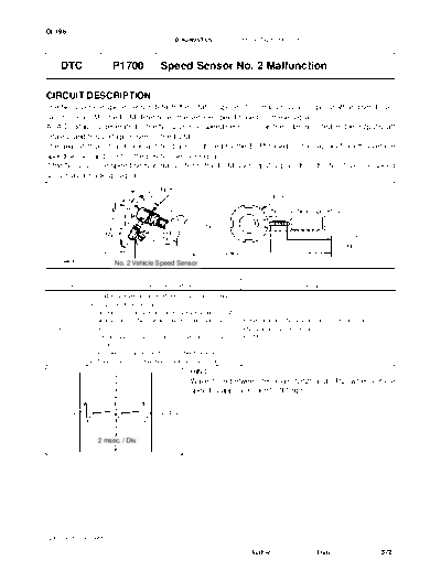
The No. 2 vehicle speed sensor detects the rotation speed of the transmission output shaft and sends sig-
nals to the ECM. The ECM determines the vehicle speed based on these signals.
An AC voltage is generated in the No. 2 vehicle speed sensor coil as the rotor mounted on the output shaft
rotates, and this voltage is sent to the ECM.
The gear shift point and lock-up timing are controlled by the ECM based on the signals from this vehicle
speed sensor and the throttle position sensor signal.
If the No. 2 vehicle speed sensor malfunctions, the ECM uses input signals from the No. 1 vehicle speed
sensor as a back-up signal.
                                           Rotor
                                                                                          Rotor
                                                                                         No. 2 Vehicle Speed Sensor


                                                                                                                       ECM

                        No. 2 Vehicle Speed Sensor                                                                                    D00010


  DTC No.                       DTC Detecting Condition                                                Trouble Area
              All conditions below are detected 500 times or more continu-
              ously (2 - trip detection logic).
              1. No signal from No. 2 vehicle speed sensor is input to ECM
                  while 4 pulses of No. 1 vehicle speed sensor signal are     S Open or short in No. 2 vehicle speed sensor circuit
   P1700          sent.                                                       S No. 2 vehicle speed sensor
              2. Vehicle speed: 9 km/h (5.6 mph) or more for at least 4 se-   S ECM
                  conds.
              3. Park/neutral position switch: OFF (Other than P or N)
              4. Transfer position: Other than N position (A340F only)

                                                        HINT:
                                                        Wave from between terminals SP2+ and SP2- when vehicle
                                                        speed is approx. 60 km/h (37 mph).

         0V                              5 V / Div.


                 2 msec. / Div.
                                              AT8761


2002 4RUNNER (RM887U)

                                                                                 Author :                     Date :                    372
                                                                                         DI-197
                                     DIAGNOSTICS   -   AUTOMATIC TRANSMISSION

WIRING DIAGRAM

                                                                        ECM


                                     Y-R                         23 SP2+
                                                                E10
                    1
                        No. 2
                        Vehicle Speed Sensor
                    2                                            22 SP2-
                                      W-R
                                                                E10


                                                                                          D10509


2002 4RUNNER (RM887U)

                                                             Author :           Date :    373
DI-198
                                   DIAGNOSTICS   -   AUTOMATIC TRANSMISSION

INSPECTION PROCEDURE

   1      Check vehicle speed value or resistance between terminals SP2+ and SP2- of
          ECM.

                                         When using OBD II scan tool or hand-held tester:
                                         PREPARATION:
                                         (a) Remove the DLC3 cover.
                                         (b) Connect an OBD II scan tool or hand-held tester to the
                                               DLC3.
                                         (c) Start the engine and turn OBD II scan tool or hand-held
                                               tester main switch ON.
                                         CHECK:
                                         Drive the vehicle and read vehicle speed value.
                                         OK:
                                               Vehicle speed matches tester speed value.
                                         When not using OBD II scan tool or hand-held tester:
         SP2+    SP2-
                                         PREPARATION:
                                         Disconnect the connector from the ECM.
                                         CHECK:
                                         Check resistance between terminals SP2+ and SP2- of ECM.
                                         OK:
                                               Resistance: 560 - 680  at 20
◦ Jabse Service Manual Search 2026 ◦ Jabse Pravopis ◦ onTap.bg ◦ Other service manual resources online : Fixya ◦ eServiceinfo