Service Manuals, User Guides, Schematic Diagrams or docs for : . Car Manuals Toyota 4Runner 1996-2003 Approved SIL techinfo.toyota.com ileaf 02toyrm 02toypdf 02rmsour 2002 024runne em5vzfe cylblo disa
<< Back | HomeMost service manuals and schematics are PDF files, so You will need Adobre Acrobat Reader to view : Acrobat Download Some of the files are DjVu format. Readers and resources available here : DjVu Resources
For the compressed files, most common are zip and rar. Please, extract files with Your favorite compression software ( WinZip, WinRAR ... ) before viewing. If a document has multiple parts, You should download all, before extracting.
Good luck. Repair on Your own risk. Make sure You know what You are doing.
Image preview - the first page of the document
>> Download disa documenatation <<
Text preview - extract from the document
                                                                                          EM-81
                        ENGINE MECHANICAL (5VZ-FE)   -   CYLINDER BLOCK
                                                                                           EM0Z7-01


                                            DISASSEMBLY
                                            1.    M/T:
                                                  REMOVE FLYWHEEL
                                            2.    A/T:
                                                  REMOVE DRIVE PLATE
                                            3.    REMOVE REAR END PLATE
                                            4.    INSTALL ENGINE TO ENGINE STAND FOR DIS-
                                                  ASSEMBLY
                                            5.    REMOVE TIMING BELT AND PULLEYS
                                                  (See page EM-13 )
                                            6.    REMOVE CYLINDER HEADS (See page EM-29 )


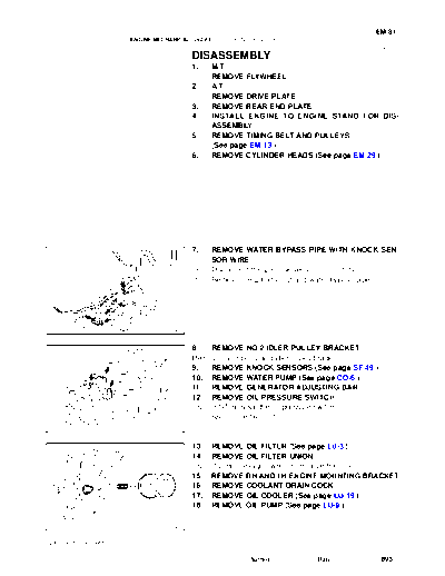
                                            7.    REMOVE WATER BYPASS PIPE WITH KNOCK SEN-
                                                  SOR WIRE
                                            (a)   Disconnect the 2 knock sensor connectors.
                                            (b)   Remove the 2 bolts, nut and water bypass pipe.


                                   P21463


                                            8.   REMOVE NO.2 IDLER PULLEY BRACKET
                                            Remove the 3 bolts and idler pulley bracket.
                                            9.   REMOVE KNOCK SENSORS (See page SF-49 )
                                            10. REMOVE WATER PUMP (See page CO-6 )
                                            11. REMOVE GENERATOR ADJUSTING BAR
                                            12. REMOVE OIL PRESSURE SWITCH
                                            Using SST, remove the oil pressure switch.
                                                 SST 09816-30010
                                   P21465


                                            13. REMOVE OIL FILTER (See page LU-3 )
                                            14. REMOVE OIL FILTER UNION
                                            Using 12 mm hexagon wrench, remove the union.
                                            15. REMOVE RH AND LH ENGINE MOUNTING BRACKET
                                            16. REMOVE COOLANT DRAIN COCK
                                            17. REMOVE OIL COOLER (See page LU-19 )
                                            18. REMOVE OIL PUMP (See page LU-9 )

                                   P21466


2002 4RUNNER (RM887U)

                                                               Author :    Date :          893
EM-82
                        ENGINE MECHANICAL (5VZ-FE)   -   CYLINDER BLOCK

                                            19.   REMOVE REAR OIL SEAL RETAINER
                                            (a)   Remove the 6 bolts and retainer.
                                            (b)   Using a screwdriver, remove the oil seal retainer by plying
                                                  the portions between the oil seal retainer and main bear-
                                                  ing cap.


                                   EM5228


                                            20. CHECK CONNECTING ROD THRUST CLEARANCE
                                            Using a dial indicator, measure the thrust clearance while mov-
                                            ing the connecting rod back and forth.
                                                  Standard thrust clearance:
                                                  0.150 - 0.330 mm (0.0059 - 0.0130 in.)
                                                  Maximum thrust clearance: 0.380 mm (0.0150 in.)
                                            If the thrust clearance is greater than maximum, replace the
                                            connecting rod assembly. If necessary, replace the crankshaft.
                                   P20859


                                            21.   REMOVE CONNECTING ROD CAPS AND CHECK OIL
                                                  CLEARANCE
                                            (a)   Check the matchmarks on the connecting rod and cap are
                                                  aligned to ensure correct reassembly.
                                            (b)   Remove the 2 connecting rod cap nuts.


                                   A06834


                                            (c)   Using a plastic-faced hammer, lightly tap the connecting
                                                  rod bolts and lift off the connecting rod cap.
                                            HINT:
                                            Keep the lower bearing inserted with the connecting rod cap.
                                            (d) Cover the connecting rod bolts with a short piece of hose
                                                   to protect the crankshaft from damage.
                                            (e) Clean the crank pin and bearing.
                                            (f)    Check the crank pin and bearing for pitting and scratches.
                                   P20865   If the crank pin or bearing is damaged, replace the bearings. If
                                            necessary, grind or replace the crankshaft.
                                            (g) Lay a strip of Plastigage across the crank pin.
 Plastigage
                                            (h) Install the connecting rod cap with the 2 nuts.
                                                   (See page EM-98 )
                                                   Torque:
                                                   1st: 25 N
◦ Jabse Service Manual Search 2026 ◦ Jabse Pravopis ◦ onTap.bg ◦ Other service manual resources online : Fixya ◦ eServiceinfo